Updated:
It’s tempting to think of an aircraft as a car – fill the seats, pack the baggage compartment, and go.
But unlike land vehicles, the amount of weight and where we place it considerably impacts how the airplane flies. If you improperly load the aircraft, it may struggle to take off or be difficult or impossible to control.
If weight and balance concepts like center of gravity seem puzzling, don’t worry. In this article, we’ll start with the basics and work our way up to calculations.
Key Takeaways
- Learn why weight and balance management is so critical – and what you need to do to stay legal.
- See how an aircraft’s flight characteristics change just by moving the CG a few inches.
- Learn how to use the computational method to determine the aircraft’s CG and see if it’s within safe limits.
- Save time by using formulae to calculate new CG positions after adding, removing, or shifting weight.

Private Pilot
Study Sheet

Grab a printable PDF that highlights must-know PPL topics for the written test and checkride.
- Airspace at-a-glance.
- Key regs & V-speeds.
- Weather quick cues.
- Pattern and radio calls.
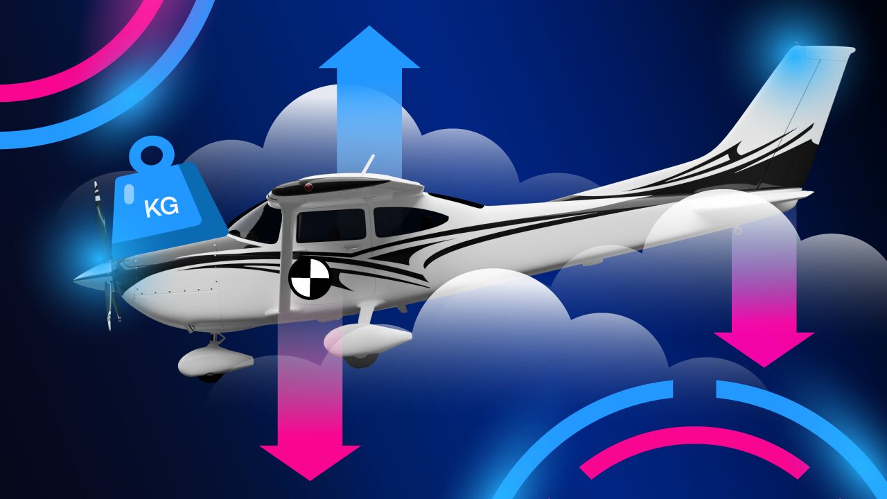
The Importance of Weight and Balance
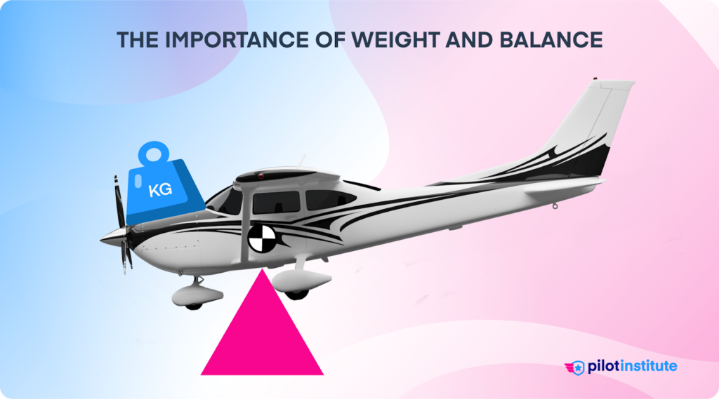
Manufacturers design aircraft to operate in a variety of missions. Most aircraft can fly short distances with heavy loads and further with light loads. While this design allows flexibility, it also makes it easy to overload the aircraft. That’s why pilots need to be careful about their aircraft’s weight.
If you load your aircraft with full fuel, passengers, and cargo, it’s likely to be severely overloaded. In fact, it might not even make it off the ground!
Even if your aircraft isn’t overweight, the position of the weight affects how it flies. If the weight isn’t distributed correctly, the aircraft will be unstable in flight. Lateral and longitudinal balance are both important. However, an aircraft fuselage’s long, thin shape makes longitudinal balance more critical.
Aircraft weight and balance data is so crucial that having it onboard is a legal requirement. If you get ramp checked, you’ll need to show it to the inspector.
Take weight and balance seriously. Countless accidents have occurred because pilots skipped their preflight calculations. Read the NTSB’s safety alert about the consequences of ignoring weight and balance here.
Weight
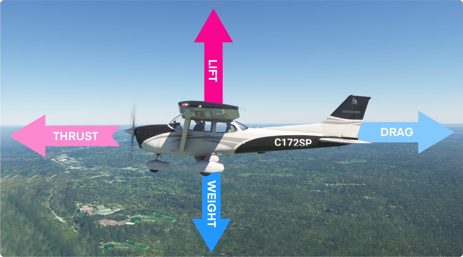
Weight is one of the four fundamental forces acting on an aircraft. It always points straight toward the Earth’s surface. For an aircraft to remain airborne, the lift generated by its wings must always equal or exceed its weight.
Lift is a dynamic force; it’s not solely dependent on the size of the wings. The speed at which air flows over the wings has the biggest impact on lift. For fixed-wing aircraft, lift is proportional to the square of the airspeed.
Aircraft generally cruise at high airspeeds where sufficient lift is easier to maintain. However, airspeeds are significantly lower during takeoff and landing. At these times, the margin between aircraft weight and available lift narrows. Weight management is especially critical during these phases of flight.
Let’s see what happens when an aircraft attempts to fly overloaded.
Takeoff and Climb
The extra weight means the aircraft needs more lift to get off the ground, raising the takeoff speed. This, in turn, means that the aircraft needs more runway to take off. Without adequate thrust or runway length, takeoff can become impossible.
If the aircraft does manage to get airborne, it will struggle to climb. The reduced margin between weight and available lift cuts the aircraft’s rate and angle of climb.
Cruise
Heavy aircraft cannot fly as high or as far.
For a given flight condition, a heavy aircraft must fly at a higher angle of attack (AOA) than a lighter aircraft. The increased AOA provides the aircraft with the extra lift required to stay aloft, but it comes at a cost. The larger AOA increases induced drag.
The extra drag “steals” engine power, leaving less to lift and propel the heavy aircraft. Increasing thrust to counteract the drag requires more fuel, shortening the aircraft’s range.
As the climb continues, the engine and wing lose performance as air density decreases. Eventually, the engine reaches its altitude limit. If the aircraft is already at best climb speed, the pilot has to increase the AOA to maintain lift. This creates even more drag.
At this point, climbing is impossible. The pilot must descend and choose a lower, more efficient cruising altitude or risk a stall.
Approach and Landing
As the aircraft slows for the approach, it gets increasingly difficult to manage. The pilot faces decreased maneuverability due to sluggish controls. The higher stall speed requires a faster approach.
Overweight landings have their own challenges. As the brakes struggle to stop the fast and heavy aircraft, the pilot risks a runway overrun. Increased loads on the aircraft structure can damage or collapse the landing gear.
Should the pilot need to perform a go-around, the aircraft will struggle to climb.
Balance
Longitudinal Balance
Weight distribution within the aircraft is just as important as the total weight.
The location of every component and item onboard impacts the aircraft’s balance. If you sum all the weights relative to their positions, you’ll end up with a single point: the center of gravity (CG). The CG is where the aircraft would balance if suspended at that point.
Like weight’s relation with CG, we can sum up the lift from the wings to a single location: the center of lift. Most airplanes have their center of lift close to the wing chord’s midpoint, but the location changes with the angle of attack.
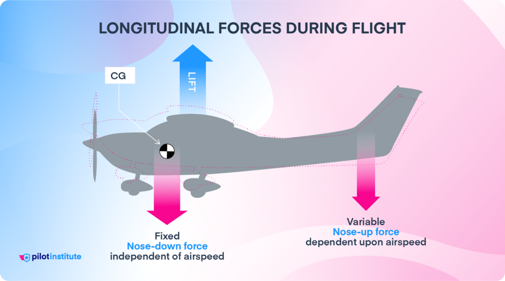
Manufacturers design airplanes to have the CG slightly forward of the center of the lift. This forward CG placement creates a nose-down force independent of airspeed. Of course, without a way to counteract this nose-down force, the airplane won’t get off the ground.
The airplane’s horizontal stabilizer provides the necessary balancing force. It works like an upside-down wing, creating downward lift that raises the nose. We adjust this nose-up force with the elevator to control the aircraft’s pitch. The faster the airplane flies, the more force the stabilizer can generate.
The CG’s position relative to the center of lift affects longitudinal stability. A CG slightly forward of the center of lift gives the airplane positive static stability. If disturbed, it will naturally return to level flight. As you might imagine, we want our airplane to respond like this.
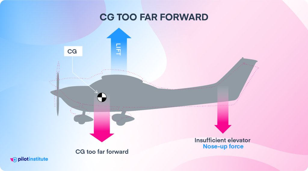
However, if the CG is too far forward, the airplane becomes challenging to control. The horizontal stabilizer struggles to provide enough force to raise the heavy nose. This makes rotating during takeoff and flaring while landing difficult or sometimes impossible.
Another issue with a too-far-forward CG is reduced efficiency. The horizontal stabilizer must provide more nose-up force to balance the CG nose-down force. The increased lift from the stabilizer generates induced drag. But that’s not the only drawback.
Since the nose-up force points downward, it effectively increases the aircraft’s weight. A heavier airplane needs a higher angle of attack to sustain flight, which creates even more drag. The higher angle of attack also increases the stall speed.
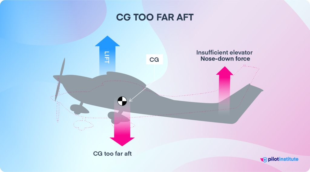
A CG that is too far aft is efficient but less stable. The flight controls become overly sensitive and twitchy. If the pilot isn’t careful, they could easily overstress the airframe.
At slow airspeeds, the horizontal stabilizer might not generate enough nose-up force. Stall recovery becomes challenging. A spin can become flat, making recovery difficult or impossible.
Lateral Balance
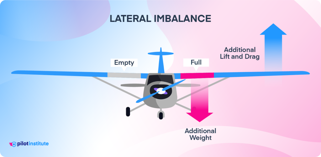
Although longitudinal balance is the greater concern, a lateral imbalance also causes instability.
In small aircraft, lateral instability is typically caused by fuel mismanagement. Airplanes have fuel tanks in each wing. If the fuel in one wing’s tank drops too far below the other, the imbalance creates a yawing moment.
The pilot will need to use the ailerons (or aileron trim, if equipped) to keep the airplane level. This control input reduces efficiency by increasing drag. Pilots must ensure they burn fuel equally from each tank to prevent this issue.
Principles of Weight and Balance
Aircraft Weight Concepts
Aircraft have multiple definitions for weight. Here are the terms you need to know.
| Aircraft Weight Terms | |
| Standard Empty Weight | The weight of a standard airplane. It includes the airframe, engine, fixed equipment, unusable fuel, full oil, and full hydraulic fluid. |
| Basic Empty Weight (BEW) | Standard Empty Weight plus any special and optional equipment installed on the aircraft. |
| Payload | The weight of the passengers, their baggage, and any cargo carried on the flight. |
| Maximum Gross Weight (MGW) | The maximum authorized total weight of the aircraft. |
| Maximum Takeoff Weight (MTOW) | The maximum weight allowed at takeoff. Limited by structural or runway length considerations. |
| Maximum Ramp Weight | The maximum weight allowed for ground operations. It includes the weight of startup, taxi, and runup fuel. |
| Zero Fuel Weight (ZFW) | The total weight excluding usable fuel. |
| Maximum ZFW (MZFW) | Max weight allowed with no fuel onboard. Limited by the aircraft’s structural rigidity. |
| Maximum Landing Weight (MLW) | The maximum weight for landing is based on the stress of impact on the gear. |
| Useful Load | The weight of the crew, passengers, baggage, cargo, and usable fuel. |
The starting point for aircraft weight calculation is the basic empty weight. No two aircraft will have exactly the same basic empty weight. Even among identical aircraft models, slight variations create differences in weight. Any modifications, such as new instrumentation, will require a basic empty weight recalculation.
A mechanic determines the basic empty weight by weighing the aircraft on scales. The resulting weight is specific to that particular tail number only.
The difference between the maximum and basic empty weights is the useful load. The useful load lets us know how much fuel, passengers, and cargo we can bring.
However, being within weight limits does not mean the aircraft is within CG limits.
Center of Gravity Concepts
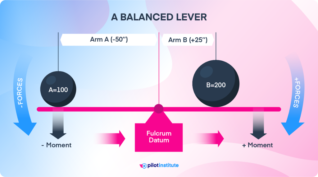
Aircraft balance works on the principle of levers.
The easiest way to understand this concept is to imagine a seesaw. The seesaw balances on a point called a fulcrum. The weight of people sitting on either end exerts a force that causes the seesaw to rotate about the fulcrum.
We call this rotational force a moment. The distance of each weight from the fulcrum is the arm. The moment is the product of the weight and the arm. The further away the people sit from the seesaw’s fulcrum, and the heavier they are, the greater the moment.
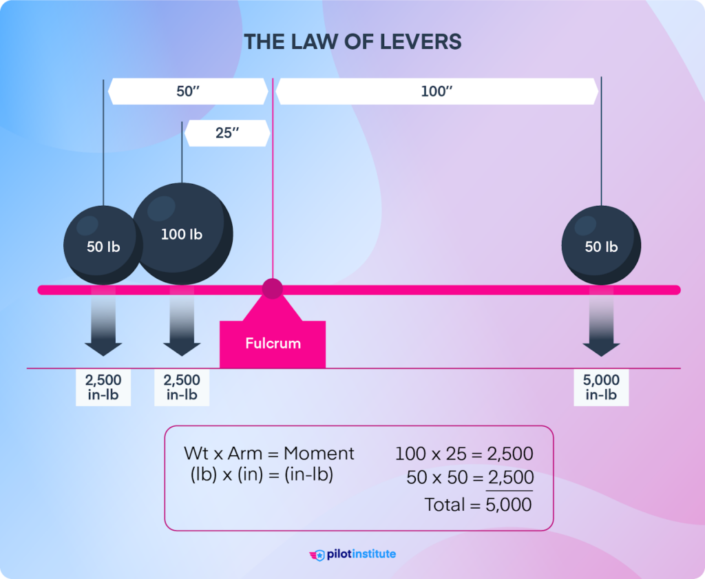
The Law of Levers states that a lever will balance about a pivot point if the moments are equal on both sides. A lighter weight further from the fulcrum can balance a closer, heavier weight.
While the seesaw has a physical fulcrum, an airborne aircraft pivots around the CG.
Like our seesaw, the weight of each aircraft component generates a moment. When calculating the CG, we must ensure these rotational forces are within limits.
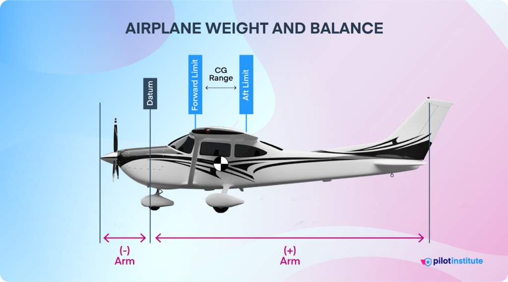
Since our goal is to locate the aircraft’s CG, we can’t use it as our reference point. We don’t know where it is!
Instead, we measure each arm from a datum. A datum is simply an imaginary reference point established by the manufacturer. For example, a Cessna 172’s datum is by the engine firewall. Common alternate locations include the wing’s leading edge or the aircraft’s nose.
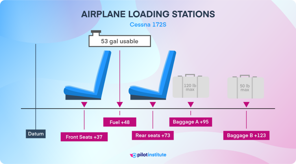
It would be exhausting to use a tape measure to determine the arm of every person and bag for each flight. Thankfully, manufacturers provide fixed locations called stations to make calculations easier. The distance from the datum defines each station.
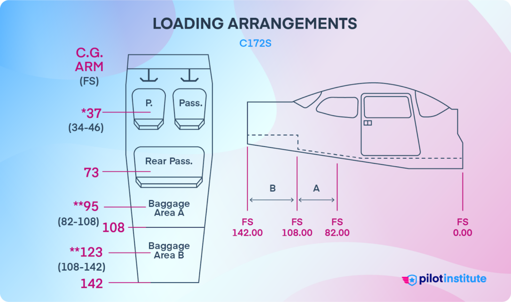
In a Cessna 172, the front seat fuselage station (FS) has an arm of 37 inches, and the arm of the rear baggage compartment is 123 inches.
Calculating Aircraft Weight and Balance
Now that we understand weight and balance fundamentals, let’s learn how to crunch the numbers.
We’ve put together a weight and balance calculator to give you a further understanding of the importance of keeping the aircraft within its limits.
Keep in mind, you still will need to understand how to manually calculate weight and balance yourself, and we will cover that next.
Weight & Balance Calculator
| Station | Arm (in) | Weight (lbs) | Moment (lb-in) |
|---|---|---|---|
| RAMP TOTAL | 0 | 0 |
There are several methods for calculating weight and balance. Aircraft manufacturers provide charts, tables, and graphs that work well. EFBs make things easier with preloaded weight profiles.
Let’s work our way through an example problem using the computational method.
The flight will be in a Cessna 172S with two people on board. The pilot weighs 130 lbs., and the front-seat passenger weighs 170 lbs. The aircraft has a full fuel load. There are 30 lbs. of cargo in Baggage Area A and 20 lbs. of additional bags on the rear seat.
First, let’s examine the aircraft data.
Manufacturers publish maximum weight, loading, and CG limitations for each aircraft model. According to 14 CFR § 23.2620, the aircraft flight manual (AFM) must include this data. The weight and balance data is the ‘W’ in the ARROW acronym for required documents for every flight.
This Cessna 172S has a BEW of 1,700 lb and a moment of 70,972 lb-in. The maximum gross weight is 2,550 lbs.
Next, calculate the moment for each station by multiplying the weight with the moment arm.
For example, here’s the calculation for the front seats at fuselage station (FS) 37.

Construct a table and fill it out for each station.
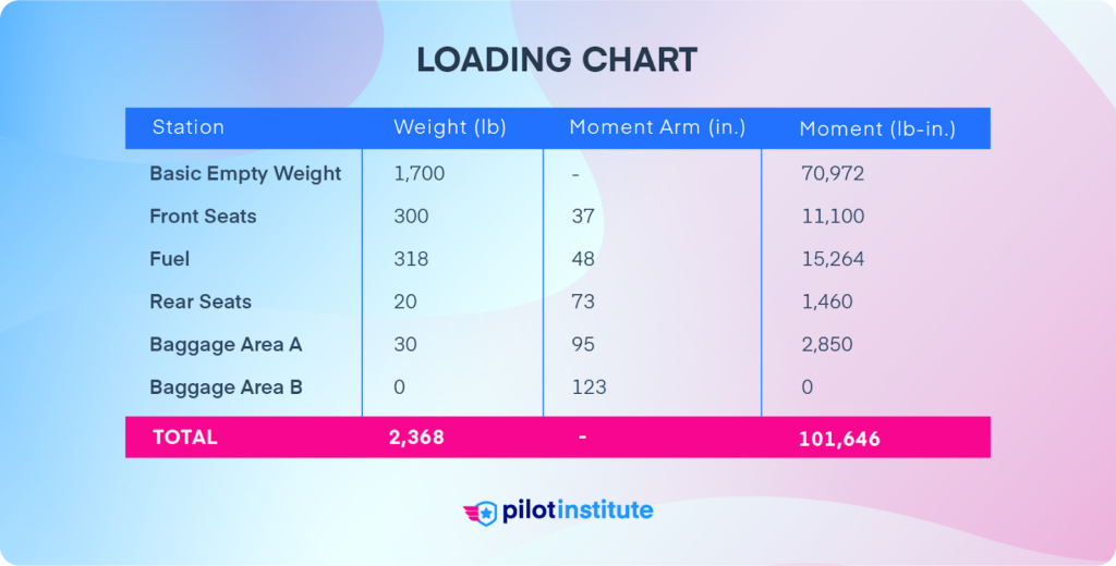
The total weight for this flight is 2,368 lbs., which is less than the maximum gross weight. We’re well within the weight limits for the C172S.
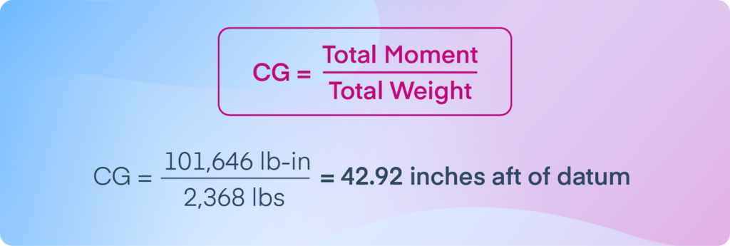
Now, let’s determine the CG.
We find the CG by dividing the total moment by the total weight.
So, is this CG within the CG envelope? We can plot our calculated CG on the chart provided by the manufacturer.
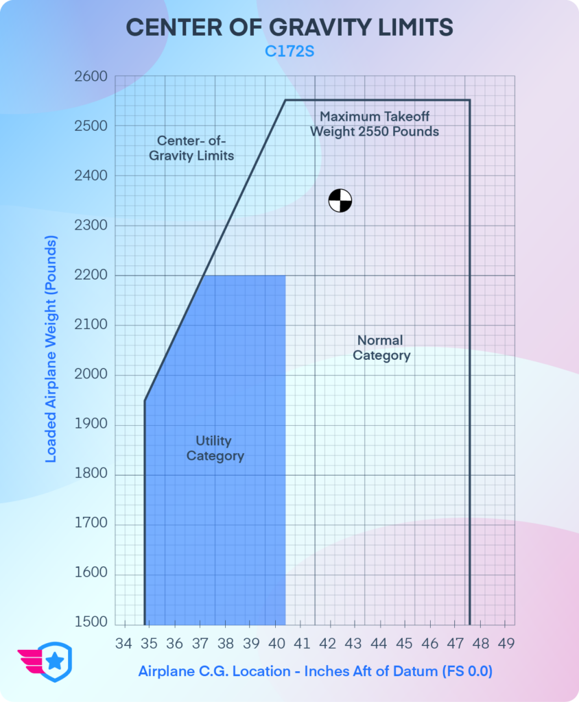
A CG location of 42.92 inches and a weight of 2,368 pounds places us well within the normal category limits.
Why does this graph have two categories?
Manufacturers certify aircraft under different categories based on their intended use.
Normal Category: An aircraft not approved for aerobatic flight, with a capacity of 9 or fewer passengers and a maximum takeoff weight of 12,500 pounds.
Utility Category: An aircraft with a maximum of 9 passenger seats plus pilot seats, weighing up to 12,500 pounds, and authorized for limited aerobatic maneuvers. This category has tighter CG restrictions.
Many aircraft, like this 172S, are certified for multiple categories. Make sure you operate your aircraft according to the rules of the category you’re flying under. Performing even limited aerobatics in the normal category can cause structural damage.
Calculating CG Shift
Weight Shift Formula
If you move weight around without adding or removing anything, you don’t have to redo the entire calculation. You can use the weight shift formula to determine the new CG.

The ∆ (delta) symbol means ‘change,’ so ∆ CG means change in CG position. Remember, if you move the weight aft, it moves away from the datum, so the change would be positive.
Let’s say we move the 20 lbs. of rear seat baggage in our example to Baggage Area B. What would be the new CG position?
The distance the weight shifts is 123 in. – 73 in. = 50 in. We can plug the numbers into the weight shift equation.

Cross-multiply the fractions.

Since the bags moved aft, the CG also shifted aft.
Therefore, 42.92 in. + 0.42 in. = 43.34 in. is our new CG location. Rechecking the CG envelope graph shows the new CG is still within limits.
Weight Added/Removed Formula
You can use another formula if you add or remove weight from the aircraft.

If we start with the original scenario and add 200 lb of baggage in Baggage Area B (station 123), here’s how to find the new CG.
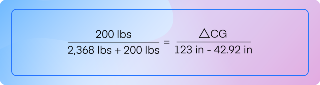
We cross-multiply again.

The new CG is 42.92 in. + 6.24 in. = 49.16 in. A check of the graph shows that the CG is now past the aft limit. Additionally, the aircraft now weighs 2,568 lbs., more than the maximum gross weight. The aircraft exceeds weight and balance limits and is NOT safe or legal to fly.
Frequently Asked Questions
- Does the center of gravity change during flight as fuel burns off?
Yes. As fuel is consumed, both weight and moment change, which shifts the CG. In most small GA aircraft, the fuel tanks sit close to the CG, so the shift is minimal. Still, you should calculate CG for both takeoff and landing conditions to confirm you stay within the envelope for the entire flight.
- Do I have to calculate weight and balance before every single flight?
Yes. The loading changes every time you fly with different passengers, fuel loads, or cargo. Even if you flew the same airplane yesterday, a different passenger or a few extra bags can push you outside CG limits. Skipping this step has caused real accidents.
- What should I do if my weight is fine but the CG is out of limits?
Rearrange. Being under max gross weight does not guarantee the CG is within the envelope. Move heavier passengers to the front seats to bring a too-far-aft CG forward, or redistribute baggage. Recalculate after every adjustment until the CG falls within limits.
- Can I use estimated weights for passengers instead of actual weights?
You should use actual weights whenever possible. Small rounding errors at each station can add up to a significant error in your final CG calculation. If asking passengers feels awkward, keep a bathroom scale in your flight bag. For fuel, the FAA standard of 6 lbs/gallon for avgas is acceptable.
Conclusion
Understanding weight and balance calculations is instrumental to safe aircraft operation. However, mastering the concepts and calculations is not the hard part. The challenge is fighting the hazardous attitudes that can erode our preflight discipline.
Before every flight, we must ensure the aircraft is properly loaded. The risks associated with flying overweight or out of balance are too grave to ignore.
This article focused on calculating weight and balance for small aircraft. Doing the same calculation for large aircraft would be extremely complex and time-consuming. That’s why large aircraft use standard weights.
Learn more about how aircraft crew use standard weights.