-
What Are Gyroscopic Instruments?
-
What is a Gyroscope - A Breakdown of Gyroscopic Instruments
- An Axis
- A Wheel
- Gyroscope Gimbal
- Power for the Gyroscopic Rotor
-
How Do Gyroscopic Instruments Work?
- Rigidity in Space and Precession
-
The 3 Most Common Flight Instruments
- The Artificial Horizon
- The Heading Indicator
- The Turn Coordinator
-
Where Else Will I See Gyroscopes in Airplanes?
-
Final Thoughts
It should come as no surprise that flight instruments are vitally important. However, a lot is going on behind the scenes. Gyroscopes are a scientific wonder, and their properties can be utilized to great effect in airplane gyroscopic instruments. Contrary to popular belief, gyroscopes are pretty easy to understand. Today we will show you how easy it can be. Here’s your ultimate guide to gyroscopic instruments, how they work, and what they do.
What Are Gyroscopic Instruments?
The 3 main gyroscopic instruments found on aircraft are the artificial horizon, the heading indicator, and the turn coordinator. All three use gyroscopic axes to provide a datum from which the aircraft’s orientation can be measured. More advanced systems can also be found on complex aircraft.
Gyroscopes have limits, but overall, they provide a reliable solution for airplane navigational and attitude instruments.
Don’t worry if you’ve never heard of a gyroscope or are familiar with the term but don’t understand it.
You are in good company.
We will go through how a gyroscope works, its main components, and how these components are utilized in common flight instruments.
Here’s everything you need to know.
What is a Gyroscope – A Breakdown of Gyroscopic Instruments
Theoretically, a gyroscope is a spinning wheel rotating around an axis. The wheel’s inertia, a function of its speed and mass, gives the gyroscope a specific property called ‘rigidity in space’. This rigidity means that, provided it is undisturbed, the gyroscope axis will stay pointed in a given direction.
Don’t believe us?
Here’s a quick video showing the concept of a gyroscope in its most basic form
Here’s what we’ll do.
First, let’s break down the common features of most gyroscopes. Once you are familiar with the parts of a gyroscope, we’ll discuss exactly how they work.
All gyroscopic instruments contain the following parts: –
An Axis
A gyroscopic axis is vital to all gyroscopes.
Remember how we just said that a gyroscope is, essentially, a spinning wheel.
Well, for a wheel to spin, it must have something to spin around. Here’s where the axis comes in. You can consider the axis a little like the axle on a bicycle wheel. It goes straight through the center of the wheel at a 90° angle to the direction of the wheel’s rotation.
However, gyroscopes can get confusing when it comes to talking axes.
Why?
Because a single gyroscope will actually have three axes: –
- The spin axis (think of it like an axel, as just discussed)
- The input axis
- The output axis
Fortunately, when discussing aeronautical gyroscopic instruments, we always reference the spin axis and where it is aligned, making understanding gyroscopes that much easier.
A Wheel
Let’s be honest.
An axle without a wheel is just a stick.
Gyroscopes need a wheel to spin in order to establish that all-important rigidity (which we’ll tell you all about below).
For now…
All you need to know is that there is a wheel, and it needs to fulfill two criteria related to ‘rigidity’
- The greater the wheel’s mass, the greater the rigidity.
- The faster the wheel spins, the higher the rigidity.
For the more scientifically minded among you, spinning wheels, mass, and speed may start to ring a bell in the back of your mind. Combined, these two forces make up something called ‘angular momentum, which in turn is a product of inertia.
For those who aren’t scientifically minded, here’s what you need to know in simple terms…
Inertia is a function of mass and speed. The higher the inertia of an object (or a spinning wheel in a gyroscope), the more resistant it is to changes in direction.
In even simpler terms…
Imagine someone rolling a bicycle wheel towards you. Not such a big deal, right? Now imagine someone rolling a tractor wheel towards you at speed. The tractor wheel is both heavier and faster, leading to an increase in inertia. The bicycle wheel is easy to stop, the tractor wheel will resist your efforts, and it is all down to inertia.
It’s the same with gyroscopes. Those with heavier wheels and faster rotation are more resistant to directional change (which in gyroscopic instruments is something we really want).
You may also hear this wheel referred to as a rotor. Throughout this article, ‘wheel’ and ‘rotor’ will be used interchangeably, but they mean exactly the same thing.
Gyroscope Gimbal
Axes and spinning wheels are all good and well, but we need something to hold them. And that something is called a ‘gimbal’. Imagine holding a bicycle wheel on an axis between two hands.
Congratulations, you have just become a gimbal.
In aircraft gyroscopic instruments, we need something slightly more precise (and smaller) than our hands. So clever designers develop highly engineered mounts that will hold the axis. These gimbals allow free movement of the gyroscopic axis. They also allow us to orientate the gyro axis in a useful direction.
Power for the Gyroscopic Rotor
One thing that all gyroscopes need to work is a spinning motion. And, obviously, that doesn’t happen on its own.
There are a few ways that the gyro wheel can be spun up to maintain that all-important rigidity.
Most systems on light aircraft will use suction to drive the rotor. Negative pressure is created using a pump within the instrument. The result is that air is sucked from the ambient air outside. This air is directed onto the rotor, causing it to spin really fast. If this tube becomes blocked or the pump fails, the rotor may slow to the point that it doesn’t maintain rigidity.
And what happens then?
The gyro may topple. This will lead to a malfunction of gyroscopic instruments. The sole purpose of gyroscopes used in instruments is to create a datum. The instrument becomes useless if this datum can no longer be relied upon!
To summarize, a gyroscope will have the following components: –
- A rotating wheel
- An axis
- A gimbal
- A means of spinning the rotor
Remember these terms because we’ll be referencing them often as we explain how gyroscopic instruments work. Speaking of which…
How Do Gyroscopic Instruments Work?
You’ll often read complex descriptions of gyros, precession, angular momentum and axes, and many other advanced terminologies.
But…
There is a simpler way to understand how gyroscopic instruments work. It goes something like this.
All gyroscopic instruments rely on using the gyroscopic axis as a datum.
Wait, what’s a datum?
A ‘datum’ is a term you’ll find used often in aviation. It simply means a set point from which you can measure something. In the case of gyroscopic instruments, we tend to use the datum created by a gyroscopic axis to measure aspects of the aircraft’s attitude.
Want it in really simple terms? Here’s how all gyroscopic aircraft instruments work in principle: –
- We point the gyroscopic axis in a relevant direction, creating a fixed datum.
- When the aircraft moves from that datum, we measure the amount of movement or change
- The change is displayed on the flight instruments as data that the pilot can use to monitor deviation.
Simple, right?
However, truly understanding how gyroscopic instruments work requires a little more in-depth knowledge.
Rigidity in Space and Precession
Gyroscopes have a unique property called ‘rigidity in space’.
It can actually be considered a literal term. (NASA uses gyroscopes for navigation on board their spacecraft). Gyroscopic-powered instruments are great because their gimbals allow them to be pointed literally in any direction.
Or, to put it another way…
At any point in space.
Above or below the horizon, or in any given direction, in three dimensions. Ideally, we want the gyroscope to stay pointed in the direction we aim it. The more resistant to movement the gyro is, the better.
This resistance is called rigidity. And rigid gyros are a good thing.
However.
This behavior presents us with particular problems here on earth.
Why?
Because let’s say we point the gyro axis towards the sun and want to use that as our datum. As you’ll no doubt know, the earth’s rotation means that the sun appears to ‘move’ across the sky. Provided the gyro is kept spinning and not disturbed, its axis will stay pointed towards the sun!
The gyro axis and the sun stay ‘fixed’, but the earth’s surface doesn’t! So, the gyro axis may also appear to move (or, in extreme cases, ‘topple’).
In truth, the gyro axis stays aligned due to its rigidity. As we move through space, the gyro appears to topple, but it is actually us that is moving around it.
The above is an interesting concept, and there are a few things that will affect how much influence this has on gyroscopic instruments: –
- The rigidity of the gyroscope
- The latitude of the gyroscope
- The point in space to which the gyroscopic axis is oriented
Just a minute. Latitude and where we point the gyro affect how well it works?
Yes. And here’s why.
Imagine a gyroscope located on the north pole with its axis pointing vertically straight up. Because the axis matches the orientation of the earth’s axis (straight up), the gyro axis will stay where we put it.
However, imagine aligning the gyroscope spin axis horizontally while we remain standing on the north pole.
Now the axis will stay aligned towards a fixed point in space on the horizon. The gyro, to us, will appear to spin horizontally, at the same rate as the earth’s rotation (15° per hour).
There’s a name for this apparent movement.
We call it precession.
Here are a few simple rules to remember regarding precession and the apparent movement of gyroscopes: –
- A gyroscope with its spin axis aligned horizontally to a given meridian (a line running north-south) will appear to move 360° over 24 hours at the pole.
- A gyroscope with its spin axis aligned horizontally to a given meridian (a line running north-south) will show no apparent movement at the equator.
Why is the above relevant in aviation?
Because we use north as a datum, and we use a heading indicator to tell us where this datum is. The heading indicator is a gyroscopic instrument. The further north you go, the more often you need to realign it due to precession!
If the above is all a little daunting, here’s a short video where you can see it in real-time.
The 3 Most Common Flight Instruments
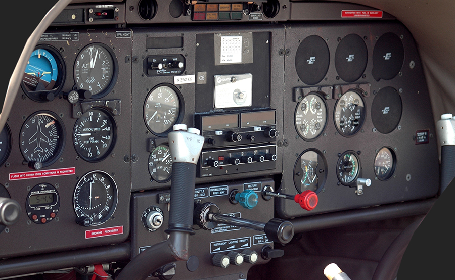
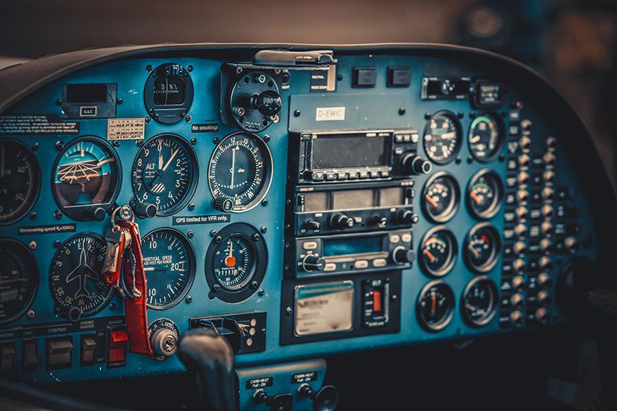
In most airplanes, you’ll find the following gyroscopic instruments. These combine with pitot-static instruments to make up the ‘six pack’ of primary flight instruments: –
- The Artificial Horizon
- The Heading Indicator
- The Turn Coordinator
Here’s a brief description of what these instruments are used for, where the gyroscopic axis is aligned and how they work.
| Instrument Name | Instrument Shows | Gyroscopic Axis Alignment |
| Artificial Horizon | Attitude and Bank | Vertical to Centre of the Earth |
| Heading Indicator | Heading | Aircraft Yaw Axis |
| Turn Coordinator | Rate of Turn* | Aircraft Pitch Axis |
*It is important to note that the turn coordinator does not show bank angle!
Here’s a detailed description of all of the above gyroscopic instruments.
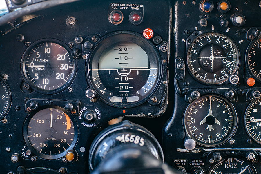
The Artificial Horizon
As the name suggests, the artificial horizon is a pictorial display of the aircraft’s attitude in relation to the earth’s horizon.
It is a disc split into two segments. The ‘blue’ represents the sky above the horizon, and the ‘brown’ represents the earth beneath the horizon.
It is used to indicate the aircraft’s attitude relative to the horizon with a small airplane symbol with a dot in the center showing whether the aircraft is nose up or nose down. It also displays the bank angle relative to the horizon.
The gyro axis is kept in a vertical state by weights at the bottom of the gimbal, so it always points towards the direction of gravity (the center of the earth).
The airplane symbol is actually fixed, and it is the disc that moves. This disc is attached to a gyroscopic gimbal. The gyroscope wheel is aligned with the horizon. Because of its rigidity, it doesn’t move, regardless of the aircraft’s attitude.
Essentially.
The aircraft symbol (and the aircraft) fly ‘around’ the fixed axis of the artificial horizon gyroscope.
Some important points to note: –
- The artificial horizon axis is aligned straight up, so it doesn’t suffer from precession
- Extreme maneuvers may cause the gyro to ‘topple.’
- Friction in the gimbal may cause the gyro rotor to slow, meaning that a bank angle or pitch attitude will be displayed, even if you are wings level.
The Heading Indicator
The heading indicator is another great example of a gyroscopic instrument. Unlike the artificial horizon, whose axis is aligned to the horizon, the heading indicator measures the deviation from a different datum.
Which is?
Magnetic north.
At the start of the flight, The gyro axis will be aligned ‘level’ to the horizon. The yaw axis (provided you are level) will match the horizon. Effectively we define the axis around which the airplane will turn. Remember, the gyroscopic axis will stay where we point it.
The easiest way to visualize this is to imagine the airplane moving around the gimbal and its aligned axis.
We rotate a moveable card in the instrument to calibrate to magnetic north on a compass. Then we can read how much the aircraft has turned away or towards it. The result in degrees is the aircraft heading.
But, remember.
With their axes aligned along the lines of longitude, Gyros are prone to precession due to the turning of the earth, so you will have to regularly cage and align your heading indicator throughout the flight.
How much does it change?
As we saw above, the precession of heading indicators is at its highest at the poles and lowest at the equator. There is a linear scale that we can apply depending on how close we are to either. We call this linear scale Sine.
Sine has its highest value at 90°. Happily, 90° latitude is the north pole. Sine has its lowest value at 0°. This 0° latitude is at the equator. Suppose the maximum rate of change is 15° per hour at the pole and 0° at the equator. In that case, we can work this into a clever formula to determine the rate of change of a heading indicator due to precession.
It looks like this.
Heading indicator precession = (Sine of your latitude) X 15
Don’t want to sit with a calculator? Don’t worry. We’ve done the hard work using the above equation, so you don’t have to. Here’s a table detailing the rate of precession at each latitude.
| Aircraft Latitude | Rate of Precession of Heading Indicator (per hour) |
| 0° | 0° |
| 5° | 1.3° |
| 10° | 2.5° |
| 15° | 3.8° |
| 20° | 5.1° |
| 25° | 6.3° |
| 30° | 7.5° |
| 35° | 8.5° |
| 40° | 9.6° |
| 45° | 10.6° |
| 50° | 11.5° |
| 55° | 12.3° |
| 60° | 12.9° |
| 65° | 13.5° |
| 70° | 14° |
| 75° | 14.5° |
| 80° | 14.8° |
| 85° | 14.9° |
| 90° | 15° |
Some Important Points To Note: –
- The higher your latitude, the more often you must align your heading indicator. This error is called ‘apparent drift’.
- Heading indicators show magnetic north, not true north.
You can read more about the heading indicator here.
The Turn Coordinator
The turn coordinator is a little bit different than your standard gyroscopic instrument. The artificial horizon and heading indicator aim to maintain a consistent datum and axis alignment.
However.
In the case of the turn coordinator, its axis alignment is short-term and dynamic.
It displays a rate of turn and slip.
If the aircraft is banked ( a fancy airplane term for one wing higher than the other) but is held on a fixed point on the horizon, the turn coordinator will display a zero rate of turn.
The axis of the gimbal is aligned with the wings (horizontally relative to the aircraft)
It measures a rate of change from this axis created by yaw. When the aircraft moves left or right, the gyro axis exerts pressure on a calibrated spring that causes the airplane symbol to show a turn in the direction of yaw.
Some Important Points to Note: –
- The horizontal axis of the turn coordinator is aligned relative to the aircraft, not the horizon
- There are two parts to this instrument. The rate of turn indicator (gyro driven) and the slip indicator (the ‘ball in the tube’, which isn’t a gyroscope instrument)
- In recent years the turn and slip indicator has been deemed to be a relatively obsolete gyroscopic instrument. The FAA has issued an advisory notice deeming the instrument to be ‘confusing’. So, don’t be surprised if you fly an aircraft with two artificial horizons installed in one panel.
Where Else Will I See Gyroscopes in Airplanes?
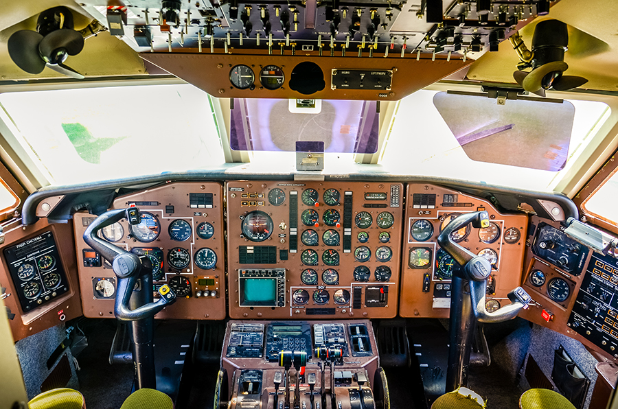
Because of their amazing properties and their ability to stay aligned to a given point, occasionally, you’ll find gyroscopic instruments used elsewhere on aircraft.
Want an example?
Big aircraft often fly over long distances without navigational aids or radio beacons.
However, they don’t just rely on ‘dead reckoning’. In fact, they use gyroscopes to ensure very accurate navigation.
Most commercial airliners use an inertial navigation system that relies heavily on gyroscopes and accelerometers. While these gyroscopes aren’t quite the same as the gyros you’ll find on light aircraft, they work similarly.
Laser ring gyros are used to fix the position of the aircraft. They are aligned to both the horizon and true north. Then, using some clever computers, the precession is monitored. By working out the precession, the aircraft computers can accurately determine the aircraft’s position.
When the aircraft accelerates, decelerates, or changes direction, accelerometers measure what has changed based on a fixed datum provided by the gyros. This change is measured and plotted on a visual display in the flight deck and fed to other aircraft computers.
Final Thoughts
While gyroscopes may require a little detailed reading, in basic terms, they are actually quite simple. Gyroscopic instruments work by using the inherent property of gyroscopes to create a datum, and deviation from this datum is measured and displayed to the pilot. Here at Pilot Institute, we love simple explanations. You’ll find plenty of them in our online flying courses. Want proof? Here’s a 100% free course that shows how easy online pilot training can be.