-
Key Takeaways
-
What Are the Six Instruments?
-
The Gyroscopic Instruments
- Pneumatic and Electrical Gyroscopes
- Rigidity in Space
- Precession
- The Attitude Indicator
- The Heading Indicator
- The Turn Coordinator
-
Pitot-Static Instruments
- The Airspeed Indicator
- The Altimeter
- Vertical Speed Indicator (VSI)
-
Conclusion
Last Updated:
When you first laid your eyes on the instruments inside an airplane, they probably went wide with a mixture of joy, confusion, and slight apprehension at the thought of having to learn how to read them.
Luckily for you and me, they are specifically designed to be intuitive, requiring only a tiny amount of information to decipher.
This article will explain the six primary instruments of every flight deck, often informally referred to as the “six-pack”.
Key Takeaways
- The six-pack includes the core flight instruments for navigation and control.
- Gyroscopic instruments rely on rigidity in space and include the AI, HI, and Turn Coordinator.
- Pitot-static instruments measure airspeed, altitude, and vertical speed.
- Mastering the six-pack is essential for safe and effective piloting.
What Are the Six Instruments?
While reading the instruments themselves are relatively straightforward, the systems behind their operation are slightly more complicated.
Furthermore, some instruments are referred to by multiple names and acronyms, which can cause unnecessary confusion.
To understand why the six primary instruments look the way they do, you need to have a basic understanding of how they function.
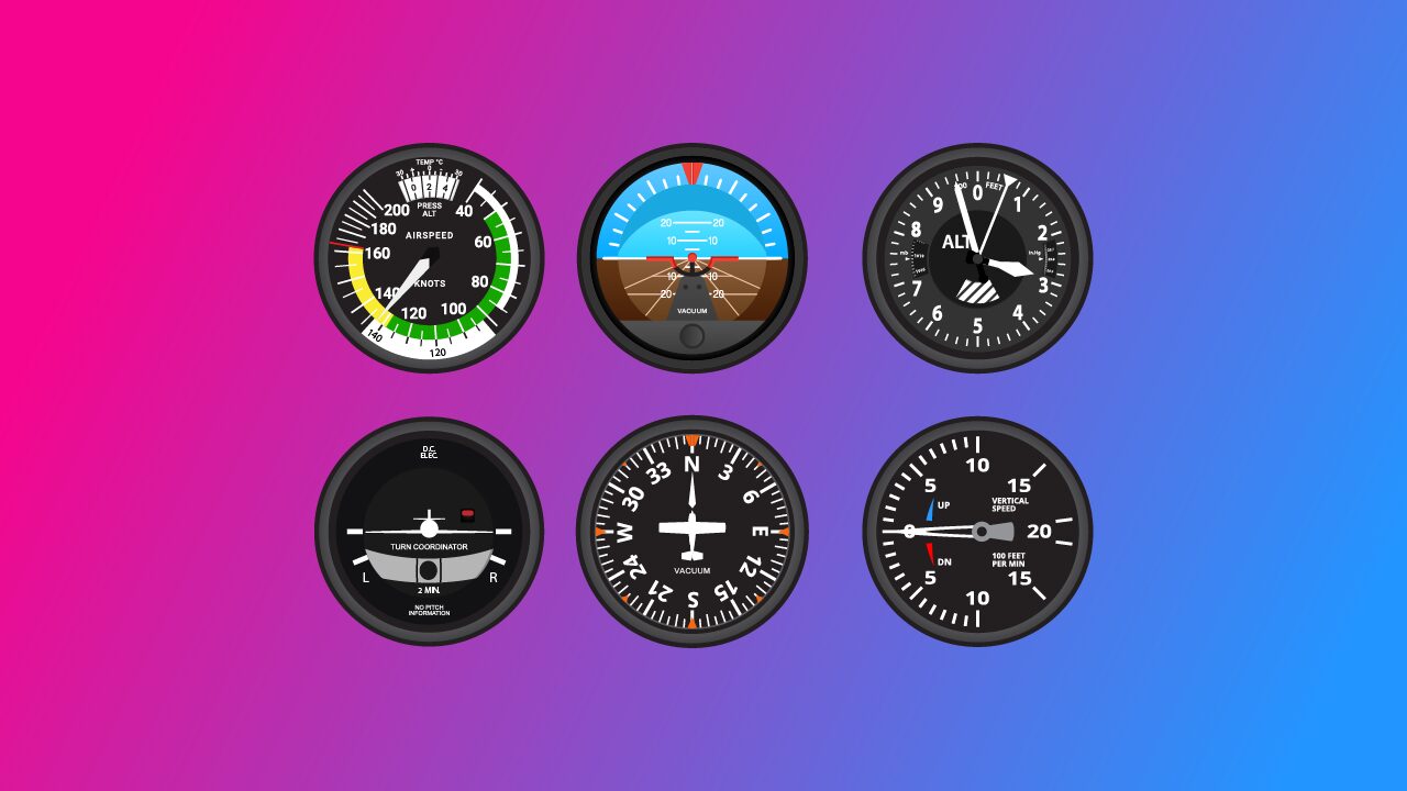
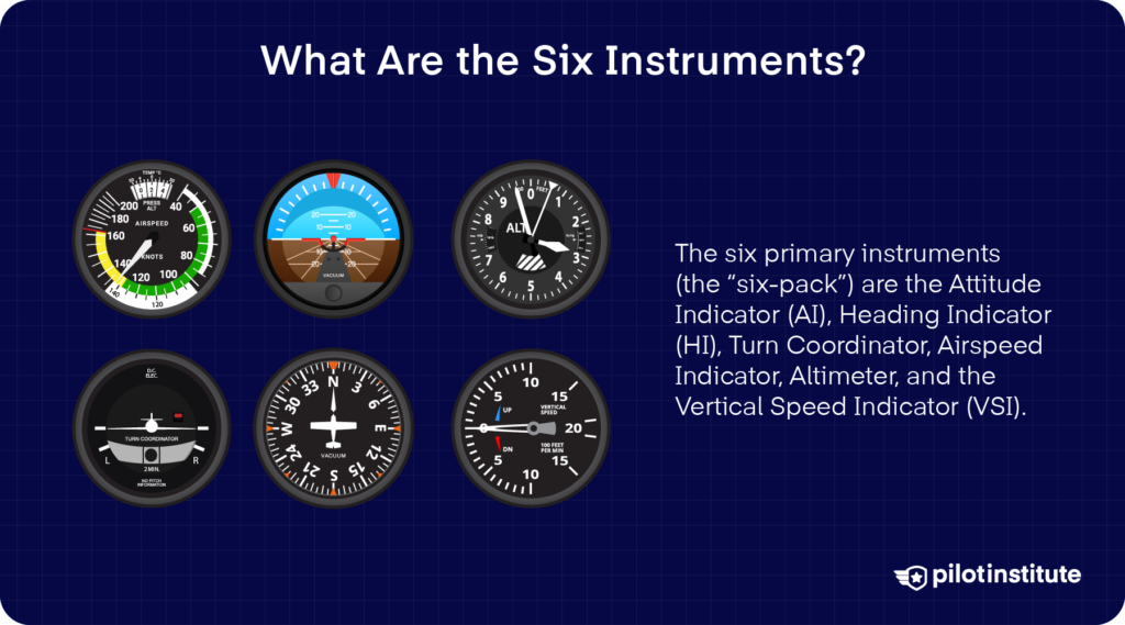
The six primary instruments (the “six-pack”) are the Attitude Indicator (AI), Heading Indicator (HI), Turn Coordinator, Airspeed Indicator, Altimeter, and the Vertical Speed Indicator (VSI).
The Gyroscopic Instruments
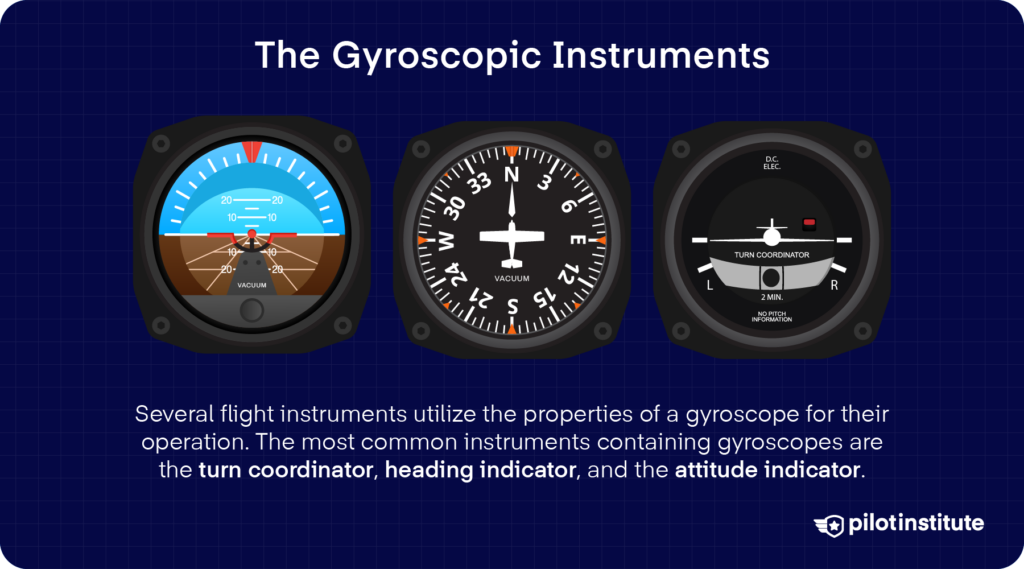
The gyroscopic instruments include the Attitude Indicator (AI), Heading Indicator (HI), and Turn Coordinator.
Pneumatic and Electrical Gyroscopes
The gyroscopic instruments use a mechanical gyroscope that is either pneumatically (vacuum) or electrically driven. The gyroscope consists of a spinning disc that rotates freely around specific axes, depending on the instrument.
In an electrically driven gyroscope (such as in the turn coordinator), the spinning disc is rotated by an electric motor. In a vacuum system, a vacuum pump driven by the engine reduces the pressure inside the instrument case. Filtered air is then directed into the case at high speed over the disc, which causes it to rotate at high speed.
Rigidity in Space
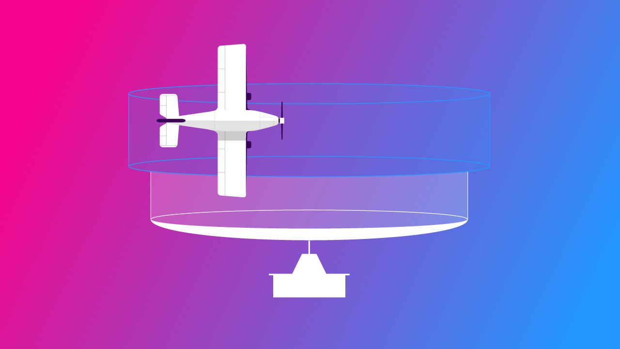
The principle that makes a gyroscope suitable for use in aircraft instruments is the gyroscope’s rigidity in space.
Rigidity in space (also known as gyroscopic inertia) is caused by the spinning disc inside the mechanical gyro. This spinning disc will maintain a constant attitude as long as no external forces act upon it. The stability of the spinning disc increases with an increase in mass or speed of the disc.
The discs inside the mechanical gyros of aircraft instruments are constructed of heavy-duty materials to allow the disc to spin at very high speeds. The gyroscopes inside these instruments spin at around 10,000 Revolutions Per Minute (RPM).
Because the spinning disc maintains a constant position in space, it can be used to determine the aircraft’s attitude relative to the spinning disc. The aircraft effectively moves around this spinning disc as the gimbals (the frames around the spinning disc) move freely.
Precession
In addition to rigidity in space, a gyroscope experiences another phenomenon: precession.
When a force is applied to a gyroscope (i.e., a spinning disc), the force will not act in the position that the force is applied but will “precess” 90 degrees in the direction of rotation of the spinning disc and act through there. In other words, if a force is applied to a spinning disc, it will “tilt” or “turn”.
Precession is primarily caused by the friction inside a gyroscope and forces experienced during maneuvers such as acceleration or deceleration.
Due to this precession, gyroscopic instruments suffer from “drift”, causing incorrect readings. Pilots must therefore constantly crosscheck gyroscopic instruments, and their indications must be adjusted accordingly.
The Attitude Indicator
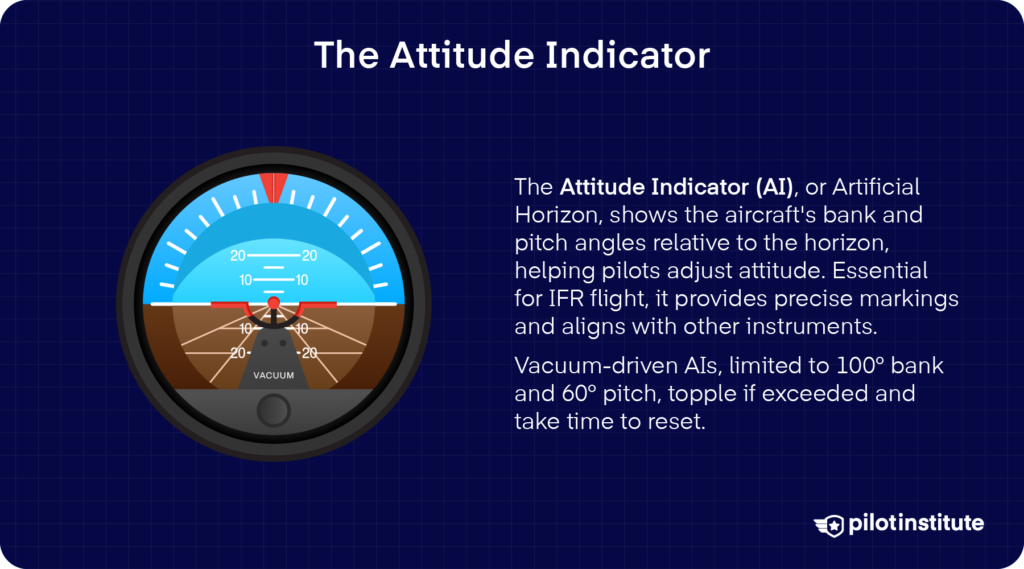
The Attitude Indicator (AI), sometimes referred to as the Artificial Horizon (AH), is the primary attitude instrument in the aircraft.
The AI provides the pilot with information on the aircraft’s bank angle and pitch angle in relation to the horizon. This allows the pilot to interpret the attitude of the aircraft and adjust accordingly.
The AI forms the basis of the instrument scan, as the AI is a good indication of what the other instruments will indicate. For example, if the AI indicates a bank angle other than the wings level, there is a good chance that the heading indicator will indicate a turn in the direction of the bank.
The AI is particularly effective during Instrument Flight Rules (IFR) flight, where the outside horizon may not be available.
The AI displays specific markings that allow the pilot to determine the pitch and bank angle the aircraft is experiencing with great accuracy.
Vacuum-driven attitude indicators are typically limited to 100 degrees of bank angle and 60 degrees of pitch angle.
If these limits are exceeded, the attitude indicator will “topple” until the aircraft returns its pitch and bank angle within limits and the AI regains a correct position. It may take a few seconds to several minutes for the gyroscope inside the AI to stabilize and the instrument to indicate correctly.
The Heading Indicator
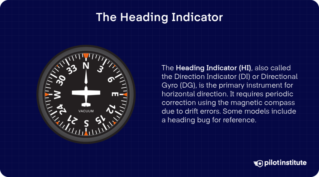
The Heading Indicator (HI), also referred to as the Direction Indicator (DI) or Directional Gyro (DG), is the primary horizontal direction indicator in the aircraft.
The HI suffers from drift errors and needs to be periodically corrected to the correct heading by using the magnetic compass.
Some heading indicators have a heading bug feature, which allows the pilot to move a colored marking to any heading on the HI for reference.
The Heading Indicator should not be confused with the Horizontal Situation Indicator (HSI), which is an evolution of the Heading Indicator that includes VHF Omnidirectional Range (VOR) and Instrument Landing System (ILS) indications.
The Turn Coordinator
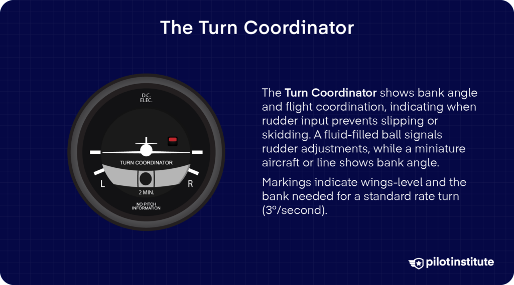
The Turn Coordinator, also known as the turn and bank indicator, is a further development of the turn and slip indicator that provides information relating to the angle of the bank and coordination of the aircraft.
The aircraft is in coordinated flight when the rudder input prevents the aircraft from slipping or skidding in a turn (similar to a car) or when its tailplane is aligned with its flight path during straight flight.
This information is displayed by a “ball” in the instrument itself. This ball is located in a tube filled with fluid and can move freely to the right and left. For example, when the ball is displaced to the left, this informs the pilot that left rudder input is required.
The bank angle information is provided either by a miniature aircraft or a vertical line that rotates in the direction of the bank. The turn coordinator has four white demarcations.
These demarcations indicate a wings-level position and the bank angle required for a standard rate turn (sometimes referred to as a “rate one turn”). A standard rate turn is at 3 degrees per second and is the preferred rate of turn during Instrument Flight Rules (IFR) operations.
Pitot-Static Instruments
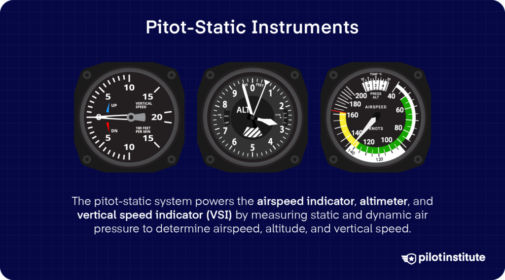
The instruments that use the pitot-static system are the airspeed indicator, altimeter, and Vertical Speed Indicator (VSI).
The pitot-static system is used to measure the static and dynamic pressure of the air during flight. This information is used to determine altitude, rate of climb or descent (i.e., vertical speed), and airspeed.
The pitot-static system consists of one or more pitot tubes and static ports. Usually, on general aviation aircraft, only one of each is required.
The pitot tube is a tube that is positioned into the relative airflow during flight. Ram air pressure (Nearly equal to total air pressure) is measured by allowing air to enter the tube through a small hole at the front. The air pressure measured by the pitot tube is sometimes referred to as pitot pressure to avoid confusion between ram and total air pressure.
The static ports are usually mounted on the fuselage of the aircraft and measure static pressure. Often multiple static ports are mounted around the aircraft for greater accuracy.
A pitot-static tube is a variation of the regular pitot tube with a static port incorporated into its design. This is achieved through holes around the probe that are not affected by the airflow directly.

Private Pilot
Study Sheet

Grab a printable PDF that highlights must-know PPL topics for the written test and checkride.
- Airspace at-a-glance.
- Key regs & V-speeds.
- Weather quick cues.
- Pattern and radio calls.
The Airspeed Indicator
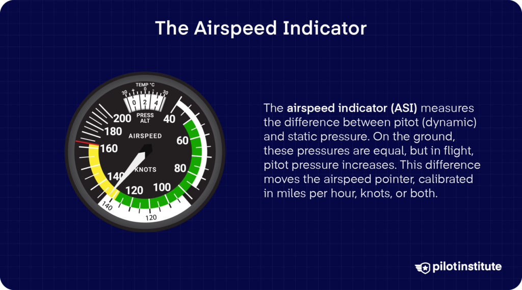
The airspeed indicator, as the name would suggest, measures the aircraft’s airspeed. Airspeed is a critical metric during flight, and the airspeed indicator is a vital piece of equipment. An aircraft’s airspeed determines its performance, and many systems, such as the flaps and landing gear, have limitations based on airspeed.
The airspeed indicator uses both the static ports and pitot tubes to determine dynamic pressure. Static pressure from the static ports is “subtracted” from the total pressure measured by the pitot tube, which provides dynamic pressure (which is a measure of airspeed). The airspeed indicator is the only pitot-static instrument that uses both the static ports and pitot tubes.
The airspeed indicator consists of colored rings within the dial. These colored rings indicate different speed ranges of the aircraft. The green ring denotes the normal operating speed range, while the white arc denotes the flap operating speed. The yellow arc represents the caution range and should only be entered in calm air, while the red arc marks the never exceed speed.
The Altimeter
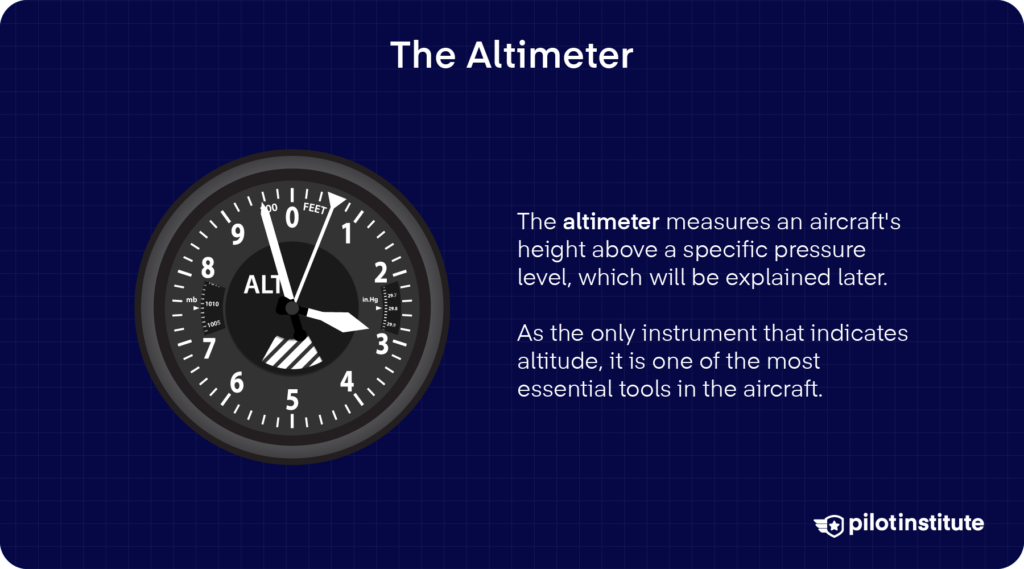
When adjusted to the correct barometric pressure setting, the altimeter (seldom referred to as an altitude meter) indicates the aircraft’s altitude above Mean Sea Level (MSL).
The altimeter uses information from the static ports of the aircraft to determine the static pressure. Aneroid capsules inside the altimeter expand or contract based on the static pressure experienced, which moves a series of gears and linkages that display altitude information.
The altimeter has two needles, one long and one short. The altimeter is read like a clock, where the short needle indicates thousands of feet, and the long needle indicates hundreds of feet.
Vertical Speed Indicator (VSI)
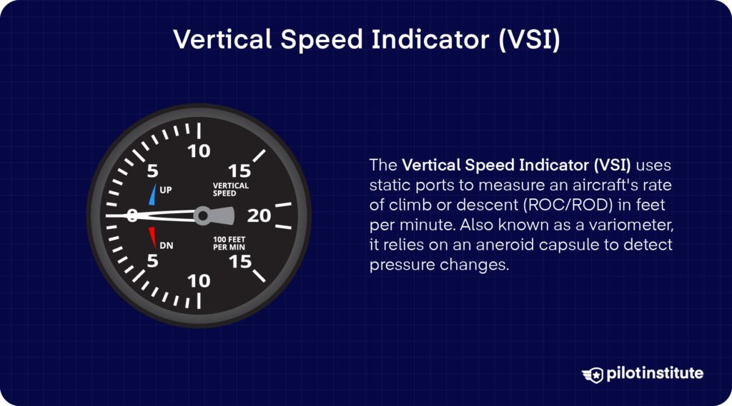
The Vertical Speed Indicator (VSI) also utilizes the aircraft’s static ports to determine an aircraft’s Rate of Climb (ROC) or Rate of Descent (ROD) in feet per minute (fpm).
The VSI is sometimes referred to as a variometer or vertical velocity indicator.
Like the altimeter, the aneroid capsule inside the VSI expands and contracts based on the change in altitude, and the rate of change of pressure is measured and displayed on the VSI as a Rate of Climb or Descent (ROC/D).
The VSI is slightly delayed and lags behind the altimeter, which should be considered when making adjustments based on the VSI. Further development of the VSI called an Instantaneous VSI (IVSI) uses accelerometers to practically eliminate the instrument’s lag.
Conclusion
The six basic instruments discussed are found in some form in every commercial aircraft. Mastering these instruments will make you a more proficient pilot and lay the groundwork for more advanced procedures. If you know your aircraft well, you will have a significantly easier (and happier) time in the air!