
-
What is an ILS?
- Decision Height
-
How does the ILS Work?
- Localizer
- Glideslope
- Approach Lighting System (ALS)
- Marker Beacons
-
ILS Categories
- Aircraft Approach Categories
- ILS Categories
-
How to Fly an ILS Approach (Step-by-Step)
- ILS Approach Chart
- Approach Procedure
-
Common Errors
- False Glide Slope
- Incorrect Course
- Wrong Frequency
- Poor Instrument Scan
-
Conclusion
Have you ever wondered how aircraft can land in the worst of conditions?
Sometimes, it seems like the pilots can’t see anything all the way down to the ground. This is most likely thanks to the ILS.
The ILS approach has revolutionized aviation and the types of weather we can fly in.
In this article, we will cover everything you need to know about the ILS. Including how it became the most reliable approach for pilots in aviation history.
What is an ILS?
You might have heard pilots talking about the Instrument Landing Systems (ILS). But what is it?
The ILS is a type of approach pilots use to land. It is a precision approach aid based on two radio beams. These beams provide the pilots with lateral and vertical guidance.
The approach starts at a certain distance and altitude from the airport. It aims to guide the aircraft to the ground. The standard approach angle of 3 degrees allows a stable profile to be flown. This means the pilots can slow and configure the aircraft for landing.
Although we have reliable GPS for many approaches today, the ILS remains relevant. Ground-based navigation aids mean we don’t have to rely on satellites.
Decision Height
You nominate a decision height (DH) for each approach. The DH is the height at which pilots must decide whether to continue the approach.
The pilots will continue the approach at DH if they are visual with the approach lights.
Different categories of ILS have different decision heights. We will go into more detail about this shortly.
How does the ILS Work?
We now know what an ILS is. But how does it work?
The ILS contains multiple components, allowing pilots to land in the worst conditions. Let’s review them.
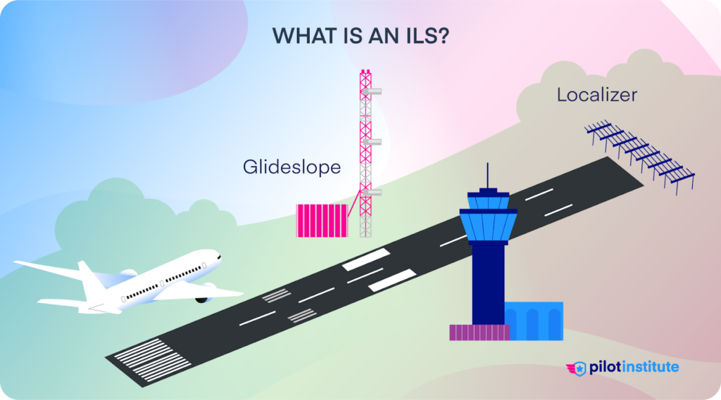
Localizer
The localizer (LOC) is a ground-based navigation aid that provides lateral guidance. The aerials are at the runway’s departure end.
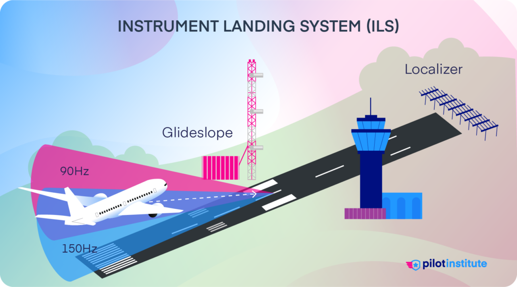
They transmit two VHF radio beams. One beam transmits slightly to the left of the centreline, the other slightly to the right. Where these beams intercept is the centreline of the approach. Meaning you are on the localizer.
The aircraft gets the lateral tracking information through receivers. The information shows the aircraft’s lateral deviation from the centreline to the pilot.
Glideslope
The glideslope (GS) provides us with vertical guidance. The aerials are in a position that provides a threshold crossing height of 50ft.
Like the localizer, the glideslope aerials also transmit two intercepting beams. One beam transmits slightly above the required vertical profile. While the other beam transmits slightly below. Where the beams intercept defines the correct glideslope profile.
The aircraft receives glideslope information through receivers. The gauges in the aircraft show the pilot the relevant information to stay on profile.
Approach Lighting System (ALS)

The ALS helps the pilot transition from instrument flying to visual flying. It consists of lights that start at the landing threshold and extend into the approach area.
The pilots can continue the approach to land when they are visual with the ALS.
Marker Beacons
These days, the ILS is generally paired with a DME (Distance Measuring Equipment). This helps the pilots verify the glideslope. It allows the pilots to compare their height at each DME distance to the promulgated chart.
DME wasn’t widely adopted when the ILS was first created. Hence why the pilots would use marker beacons.
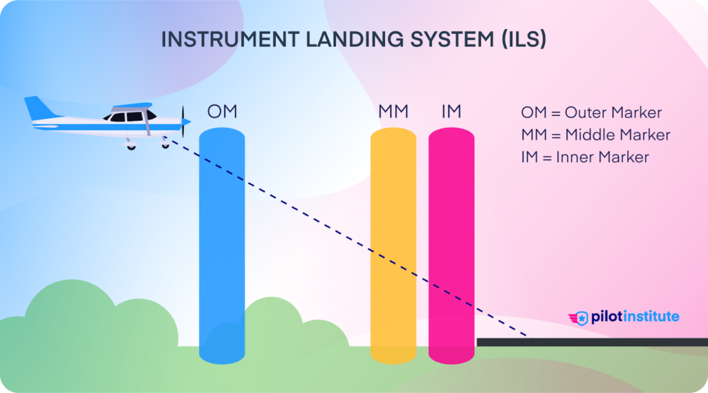
Each beacon relates to a specific position on the approach for pilots to cross-check. An audible tone or a visual light in the cockpit helps identify the position.
There can be up to three marker beacons on an approach:
- Outer Marker (flashes blue) – Represents the Final Approach Fix and/or glideslope intercept.
- Middle Marker (flashes amber) – Represents DH.
- Inner Marker (flashes white) – Represents DH for a CAT II ILS.
ILS Categories
Aircraft Approach Categories
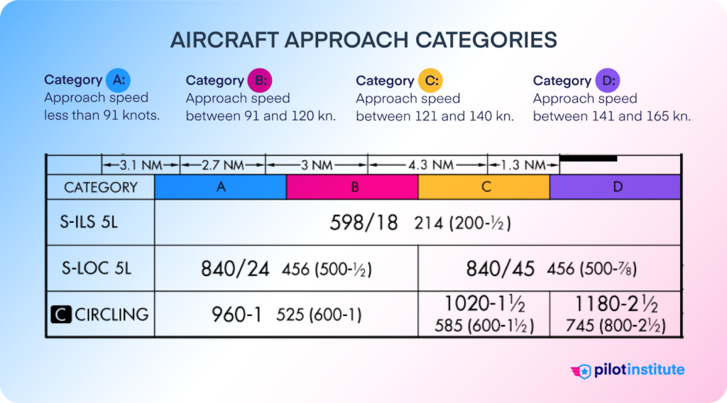
There are the categories listed on your instrument approach chart. They are as follows:
Category A:
- Less than 91 knots.
- Usually, this is small, light aircraft used in general aviation(single-engine airplanes).
Category B:
- 91 knots to less than 121 knots.
- Includes light twin-engine aircraft and some business jets.
Category C:
- 121 knots to less than 141 knots.
- Commercial airliners, like smaller regional jets.
Category D:
- 41 knots to less than 166 knots.
- Larger commercial aircraft; larger jets like the Boeing 737 or Airbus A320.
Category E(not as common):
- 166 knots or more.
- Primarily for military aircraft.
ILS Categories
There are three main categories of ILS. Which category the pilots use depends on the type of equipment the aircraft has. It also depends on the pilot’s level of training.
The higher the category of ILS, the lower the minimum required for the pilots to land. The three categories of ILS are CAT I, II, and III. There are three subcategories of CAT III ILS: A, B, and C.
Below, we’ve put together a table to show you the relevant weather minimums for each category of ILS.
| Category of ILS | Decision Height (DH) | Runway Visual Range (RVR) |
| CAT I | Not lower than 200 ft | Not less than 1800 ft |
| CAT II | Lower than 200 ft but not lower than 100 ft | Not less than 1200 ft |
| CAT III A | Lower than 100 ft or no DH | Not less than 700 ft |
| CAT III B | Low than 50 ft or no DH | Not less than 150 ft |
| CAT III C | No DH limitations | No RVR limitations |
With CAT III C, sufficiently equipped aircraft can autoland in zero visibility fog.
How to Fly an ILS Approach (Step-by-Step)
So, we know what an ILS Approach is, but how do we fly one? It might sound like a lot, but once we break it down step-by-step, it’s a lot easier than you think.
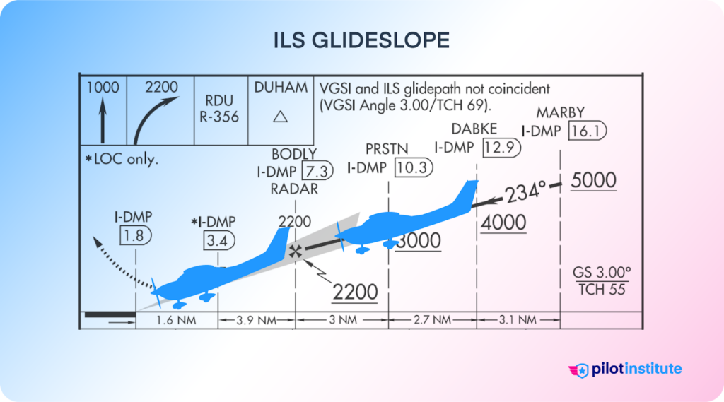
ILS Approach Chart
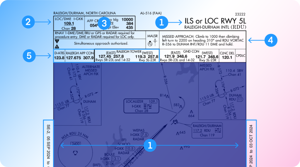
Before we can fly an ILS Approach, we must know how to read an approach chart. We have the ILS Approach for RDU Runway 5L, for this example.
You may be asking yourself, where do I begin?
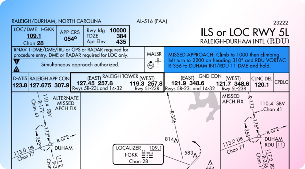
A briefing strip provides pertinent points for the ILS approach. You can find the briefing strip at the top of the Instrument Approach Chart (IAC). Let’s review this briefing strip.
- Updated—Check to make sure the approach is up to date, and for the right type of approach and the correct runway.
- LOC/DME—Tune into the localizer frequency.
- Approach Course— Set your approach course heading.
- Missed Approach—This is the missed approach procedure. If you do not get a visual of the runway at the DH, you carry out the procedure stated.
- Communication Frequencies—Double-check your frequencies, and make sure to set your back up with the tower using the appropriate frequency for the runway you intend to land on.
The picture below the briefing strip is a visual representation of the approach. The DME distances and certain altitudes are for you to validate the glideslope.
Approach Procedure
We now understand the basics of reading an approach chart (sometimes informally referred to as an “approach plate”). Let’s see how to actually fly an ILS approach.
Tuning and Identing the Localizer
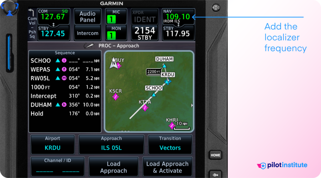
Before we start the approach, we must ensure that we have selected the correct frequency. Once we have input the localizer frequency, we need to identify it.
How do we do this?
We use the “IDENT” function in our aircraft to listen to the Morse code of the frequency. This is a button on the transponder (or Garmin) near where you input your squawk code.
The Morse code we seek will be on the approach plate. The visual representation shows this underneath the nav aid frequency.
Once this is complete, ensure that you tune the correct frequency.
If anything confused you, read more about identing in our article Transponder Modes Explained.
Setting the Course
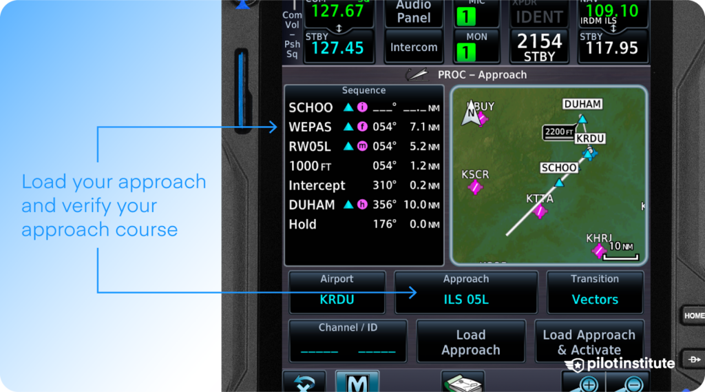
Before we intercept the approach, we must set the inbound course. You do this by using your course needle. Once you have selected the correct course you are ready to arm the approach.
Set the correct DH, which the approach plate will nominate. This is vital as you will need a reference to this height when on the approach.
Intercepting the ILS
Once cleared for the approach, you will receive vectors onto the approach.
The controller will give you a 30°-45° intercept. This allows you time to turn onto the approach and become established.
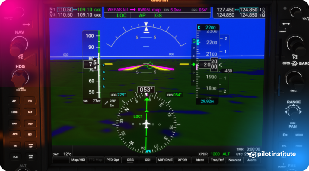
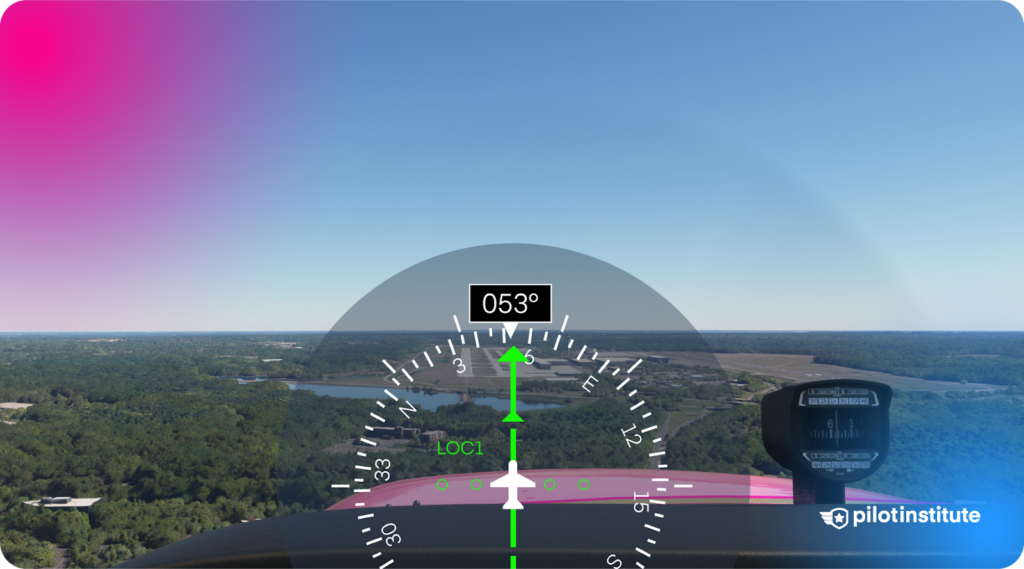
Flying the Approach
Once established on the approach, you will want to follow the ILS down to the DH.
Keep a close eye on your Course Deviation Indicator(CDI). Do not chase the needle, and talk to your flight instructor about this.
Complete check heights with the altitude advisories every few nautical miles. This verifies your glideslope profile.
Configure the aircraft for landing. When approaching your DH, be ready to transition to visual flying. If you are visual at the nominated DH, continue the approach to land. If you are still IMC, carry out the missed approach.
Common Errors
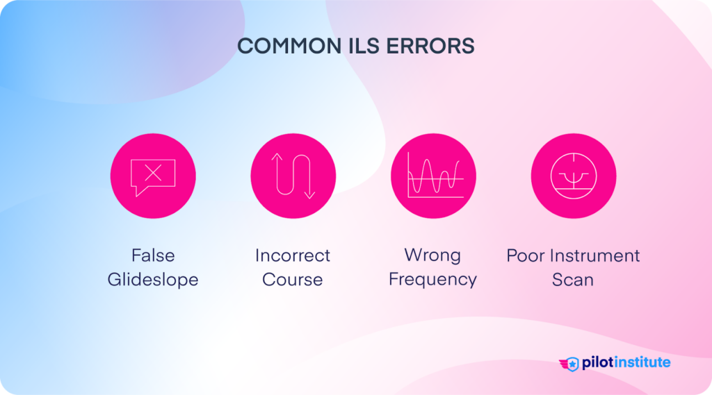
Once established on the approach, the ILS is easy to fly. However, a few errors can affect your approach.
Let’s review some of the common errors you may encounter. Knowing these will help you mitigate them when you fly an ILS.
False Glide Slope
In mountainous areas, you may sometimes get a false glide slope reading. These readings tend to happen before you are on an approach greater than 10 NM from the airport.
An erroneous glide slope capture could cause you to get low on the approach for a certain distance. So make sure you remain vigilant.
To mitigate these, continue to check the altitude advisories on your approach chart.
Incorrect Course
An incorrect course will mean you will not intercept the approach. In some advanced aircraft, you may get a master caution indicating that the wrong course has been set.
Brief the approach with detail. Cross-check the course with the approach plate to ensure the correct course is set.
Wrong Frequency
Another common error is setting the wrong localizer frequency. It is urgent to identify this when tuning the localizer.
Identifying the frequency verifies that you have set the correct frequency. It also verifies that the navigation aid is working as it should be.
Poor Instrument Scan
A poor instrument scan may cause you to deviate from the localizer and glideslope. A deviation of more than half a scale will mean you must carry out a missed approach.
Practicing a good scan on the approach will not only ensure you stay on the ILS but also keep you stable. This is crucial for any instrument approach.
Conclusion
The ILS approach has revolutionized the aviation industry. The introduction of the ILS means pilots are able to land in some of the worst conditions. Making aviation travel that much more reliable.
Although the ILS has existed for a long time, it remains one of the most used approaches worldwide. This is for a good reason.
Knowing how to fly one of these approaches will definitely enhance your flying skills.Do you know what’s even better than a perfect approach? A perfect landing. If you want to learn how to perfect your landings, check out our article on How to Improve Your Landings.