-
Key Takeaways
-
What Is an ILS Approach?
- Why Do We Need ILS?
-
What Information Does ILS Provide?
- Guidance Information
- Range Information
- Visual Information
-
What Equipment Do You Need on the Aircraft?
- Instruments
-
What Are the Categories of ILS?
-
How to Fly an ILS Approach
- Preparing for the Approach
- Getting Established on the ILS
- Descending to Decision Height (DH)
- Breaking Out for Landing
-
Using Autopilot for ILS Approaches
-
Limitations of the ILS
-
The Future of ILS
-
Conclusion
Even driving a car can be dangerous in foggy weather. So, how do pilots manage to land their aircraft safely and accurately without even being able to see where they’re going?
The ILS (Instrument Landing System) uses radio signals to help pilots align the aircraft accurately on their approach to a runway.
Let’s learn more about this system!
Key Takeaways
- ILS provides precise guidance for safe landings in low visibility.
- Correctly intercepting the localizer and glideslope ensures accuracy.
- Autopilot aids ILS approaches but needs close monitoring.
- Awareness of false courses and signal issues is critical for safety.
What Is an ILS Approach?
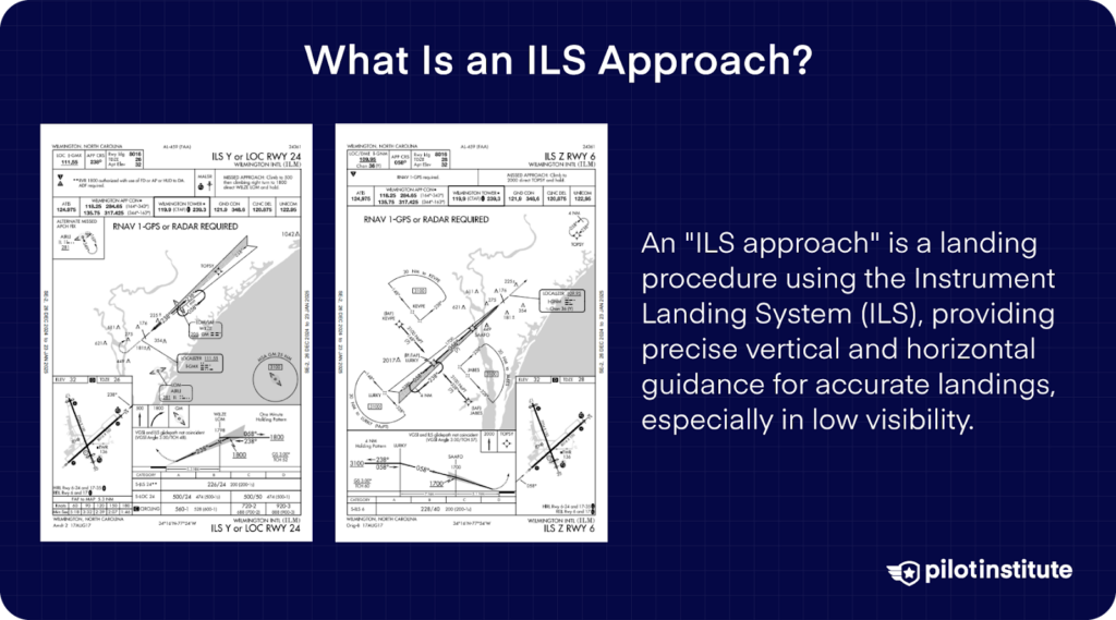
An “ILS approach” is a landing procedure using the Instrument Landing System (ILS) to guide an aircraft to the runway. While it is particularly useful in low visibility or poor weather conditions, it is not limited to such situations.
ILS relies on a ground-based navigation system that provides the pilot with both lateral (horizontal) and vertical guidance. It can help align the aircraft with the runway and descend at the correct angle.
Why Do We Need ILS?
Air travel would be significantly reduced if aircraft were limited to landing only when the weather was perfect.
An ILS approach allows pilots to land even in poor visibility caused by fog, rain, or clouds by providing precise lateral and vertical guidance.
Precision vs. Non-Precision Approaches
- Non-Precision Approaches: Only provide lateral guidance, requiring pilots to level off at a Minimum Descent Altitude (MDA) until the runway is visible.
- Precision Approaches (e.g., ILS): Include vertical guidance, allowing a continuous descent to a Decision Height (DH) where the pilot decides to land or go missed.
ILS is a reliable system that supports visual landings and enables safe landings in conditions where visual approaches are impossible.
What Information Does ILS Provide?
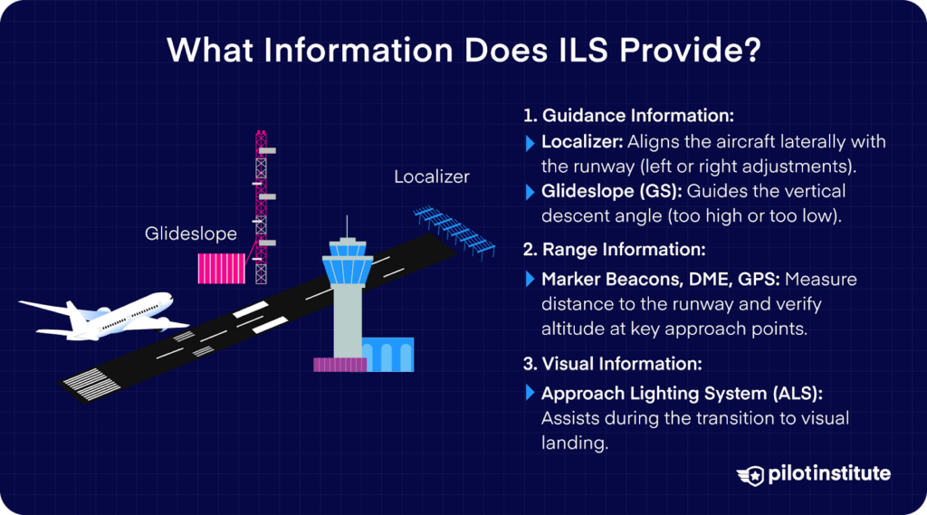
The ILS gives three types of information to the pilot. They are:
Guidance Information
- Localizer: Provides lateral guidance to align with the runway.
- Glideslope (GS): Provides vertical guidance for the correct descent angle.
Guidance information is given by the localizer and glideslope. These help the pilot align the aircraft properly with the runway for landing.
The localizer provides lateral or horizontal guidance, letting the pilots know if they need to turn left or right to correct their course.
The Glideslope gives vertical guidance, letting the pilots know if the aircraft is too high or too low on the approach.
Range Information
- Marker Beacons, DME, and GPS: Indicate distance from the runway and help verify altitude at key points.
Range information helps pilots determine their distance from the runway, which is critical for maintaining the correct altitude and approach profile. This is provided by Marker Beacons, DME, and GPS. Marker Beacons use radio signals to indicate key points along the approach, such as the outer and middle markers.
DME (Distance Measuring Equipment) calculates the slant range distance to the runway using radio frequencies. Modern IFR-certified GPS can also substitute for DME, providing precise distance information as outlined in AIM 1-2-3.
Range information is also used to adjust the aircraft configuration and prepare the aircraft for landing. Lowering flaps, extending the landing gear, and making the final decision to land or go missed are all tied to the distance remaining to touchdown.
Visual Information
- Approach Lighting System (ALS): The ALS assists pilots during the transition from instrument navigation to visual landing.
What Equipment Do You Need on the Aircraft?
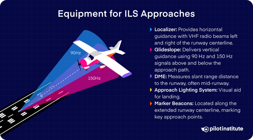
The localizer operates within a subset of the VHF (Very High Frequency) range, similar to VOR, but the underlying technology differs.
Modern NAV receivers are typically capable of decoding both VOR and localizer signals, including glideslope signals, even though these systems use distinct technical mechanisms.
The glideslope requires a UHF (Ultra High Frequency) receiver. The instruments that can display the signal readout to the pilot are the CDI and the HSI.
Navigation Receivers: VHF for the localizer, UHF for the glideslope.
Instruments
Course Deviation Indicator (CDI)
The CDI displays deviations from the localizer (lateral) and glideslope (vertical) using two moving needles. The localizer course is fixed, so the OBS knob does not affect how the CDI displays the course. However, setting the OBS for reference on an analog CDI can help visualize the approach.
- Needles indicate corrections needed: fly toward the needle to re-center it.
- Aligning the needles with reference marks means the aircraft is on course and glide path.
- Localizers are more sensitive than VORs, with full-scale deflection at 2.5° for the localizer and 0.7° for the glideslope.
- A full-scale deviation on an ILS indicates that the aircraft is significantly off-course and could be at risk of Controlled Flight Into Terrain (CFIT). Pilots must immediately correct their course when a full-scale deviation occurs.
If the CDI loses the signal, a warning flag appears, signaling unreliable data.
Horizontal Situation Indicator (HSI)
The HSI combines CDI functions with a heading indicator for enhanced situational awareness. While it operates similarly to the CDI, most modern HSIs automatically align their course pointer with the localizer front course when a valid localizer signal is received, making manual OBS adjustments unnecessary in these scenarios.
While localizers guide along a single published track, the OBS setting aids in visualizing the inbound course.
Marker Beacon Lights
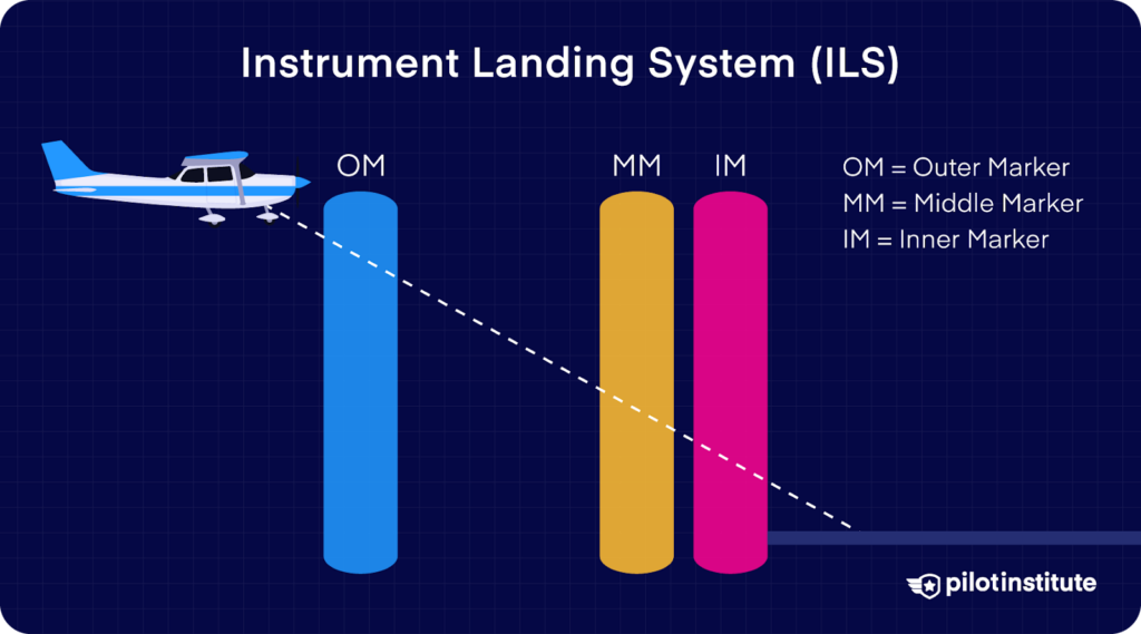
Marker beacons indicate proximity to key approach points:
- Outer Marker (O): Blue light, signals glideslope interception.
- Middle Marker (M): Amber light, marks Decision Height for Cat I ILS.
- Inner Marker (I): White light, used for Cat II ILS.
Beacon sensitivity settings allow pilots to anticipate or confirm exact positions.
Other Equipment
Other airborne equipment includes the ADF and DME instruments, in addition to receivers installed for each system. ADF uses low to medium frequency receivers and DME requires a UHF receiver.
What Are the Categories of ILS?
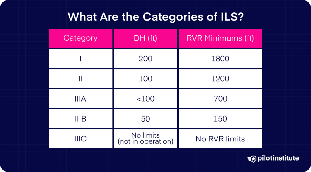
ILS categories vary based on runway equipment, aircraft capabilities, and pilot certification, with differences defined by Runway Visual Range (RVR) and Decision Height (DH). Higher categories permit landings in worse visibility and lower DHs.
- Category I: Minimum RVR of 1800 feet and DH of 200 feet.
- Category II: RVR reduced to 1200 feet and DH to 100 feet.
- Category III:
- IIIA: RVR as low as 700 feet and DH below 100 feet.
- IIIB: RVR down to 150 feet and DH at 50 feet.
- IIIC: No RVR or DH limits, though not currently in operation.
Higher categories typically require advanced equipment like autothrottles, auto-land systems, and stricter airport safeguards to prevent signal interference.
Category II and III approaches rely heavily on autopilot due to minimal reaction time at lower DHs. Category IIIC approaches are not used because zero-visibility conditions make taxiing unsafe. Learn more about these categories through our article ILS explained.
How to Fly an ILS Approach
Preparing for the Approach
- Listen to ATIS to determine the active runway and approach.
- Review the approach plate for:
- Runway length, elevation, and approach minima.
- Frequencies, missed approach procedures, and notes.
Getting Established on the ILS
- Tune to the ILS frequency and verify its Morse code identifier.
- Intercept the localizer within 30° of the published course to avoid false signals.
- Intercept the glideslope from below at the specified altitude, ensuring a smooth descent path. This allows proper alignment even if an Outer Marker is not present.
Descending to Decision Height (DH)
- Follow the glideslope to the Decision Height, typically 200 feet for Category I ILS.
- Confirm stability on the approach, make sure the aircraft maintains a constant descent rate, airspeed, and alignment with the runway centerline. Decide whether to land or execute a missed approach based on these factors.
Breaking Out for Landing
Transition to visual references, ensuring compliance with the required visual references outlined in 14 CFR 91.175.
These include identifying the runway environment, such as the runway threshold, threshold markings, or lights, and maintaining a stable approach. Use the ALS or PAPI/VASI lights, if available, for additional guidance.
Identify the runway threshold and ensure proper alignment for a safe landing.
Using Autopilot for ILS Approaches
Flying an ILS approach with autopilot, known as a coupled approach, allows the autopilot to follow the localizer and glideslope precisely.
After tuning the ILS frequency and identifying the correct signal, activating the NAV or LOC function aligns the autopilot with the localizer. The aircraft should already be established on the localizer well before the glideslope intercept point, even if an Outer Marker is not present.
Once the glideslope signal is active, switching to the Approach Hold mode ensures the autopilot follows both the lateral and vertical guidance.
The system can be “armed” to automatically engage once strong ILS signals are detected, but Approach Hold typically requires Altitude and Localizer modes to be active first.
Transferring glide path control should only occur after ensuring the autopilot is tracking the correct localizer and glideslope signals. This helps prevent the aircraft from following a false course or incorrect signal.
While coupled approaches reduce workload, the pilot must remain vigilant. The ILS is sensitive to deviations and signal issues, so be prepared to disengage the autopilot and manually correct as needed.
In simple steps:
- Engage Localizer Hold (LOC) to align with the runway course.
- Activate Approach Mode (APR) to capture and follow the glideslope.
- Monitor the autopilot, ensuring it maintains the proper descent and alignment.
- Disconnect the autopilot at the altitude specified for your aircraft’s operation, certification, and approach procedure, then perform a manual landing.
Limitations of the ILS
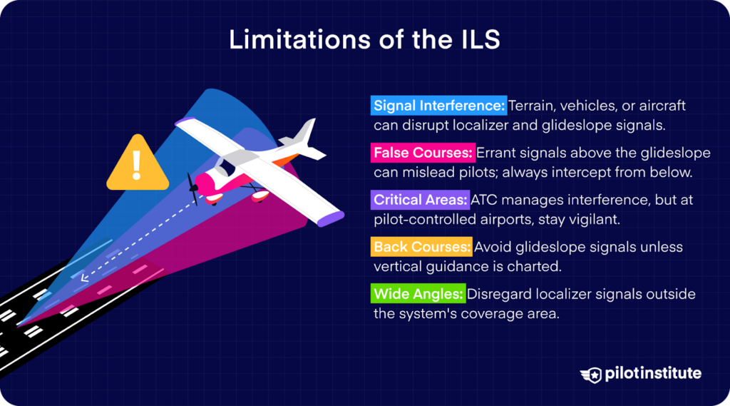
- Signal Interference: Terrain, vehicles, or nearby aircraft can disrupt localizer and glideslope signals.
- False Courses: Errant signals can cause deviations if the glideslope is intercepted from above.
- Critical Areas: ATC manages ground traffic to prevent interference near ILS equipment, but pilot-controlled airports require pilot vigilance.
The ILS, like other radio-based systems, has limitations. Signals from the localizer and glideslope can reflect off obstacles such as terrain, vehicles, or other aircraft, causing interference.
High-powered transmissions also create false courses, particularly above the real glide path, which can mislead pilots into dangerously steep descents with unreliable signals.
To avoid this, pilots must intercept the glideslope from below, as false courses don’t exist beneath the true path.
On back courses (approaches that use the reverse signal of a localizer to guide the aircraft to the runway), vertical guidance is typically unavailable unless specifically mentioned in the approach chart. Pilots should avoid relying on glideslope signals during these approaches to prevent errors.
Localizers can also produce false courses at wide angles, which appear accurate but fall outside the system’s coverage area and should be disregarded.
The Future of ILS
While the ILS remains the gold standard for precision approaches, GPS-based systems like LPV (Localizer Performance with Vertical Guidance) are becoming more prevalent due to their lower installation and maintenance costs.
These systems lack some of ILS’s limitations, such as critical area restrictions and false courses, making them suitable alternatives for smaller airports.
Conclusion
Landing in low visibility is one of the most challenging and yet rewarding aspects of flying. The ILS provides precise guidance, offering safe landings in challenging conditions.
ILS approaches are an important part of achieving an instrument rating. If you’d like to learn about other types of instrument approaches, Instrument Rating Made Easy has simple and straightforward lessons designed to help pilots.
Keep learning and keep flying!