-
Key Takeaways
-
What Is Bernoulli’s Principle?
- Types of Pressure
- The Venturi Tube: A Classic Example
-
Bernoulli’s Principle and Lift: How Wings Generate Lift
- How Bernoulli’s Principle Relates to Flight
- Pressure Differences and Lift Generation
- Flow Turning
- What Affects Flow Turning?
-
Bernoulli's Principle and Newton's Third Law
- How Does Newton’s Third Law Explain Lift?
-
Misconceptions About Lift
- Equal Transit Time Theory
- Skipping Stone Theory
- Venturi Theory
-
Practical Applications in Aviation
- Carburetors in Piston Engines
- Jet Engine Inlets
-
Importance for Pilots and Engineers
- How Do Pilots Use Bernoulli’s Principle?
- Impact on Aircraft Design
- Training and Education
-
Conclusion
Aircraft are massive, heavy machines. How do they manage to fly, supported by nothing but thin air?
Many explanations on websites, videos, and even some textbooks oversimplify or misrepresent the true mechanics of lift.
In reality, lift generation involves both Bernoulli’s principle and Newton’s third law working together.
Read on to understand Bernoulli’s principle and how it relates to lift the right way.
Key Takeaways
- Bernoulli’s principle explains how increased airflow velocity reduces pressure, contributing to lift.
- Airfoils use this principle, with faster airflow over the top creating lower pressure.
- Bernoulli’s principle also applies to how carburetors and jet engine inlets work.
- Lift results from both Bernoulli’s principle and Newton’s third law working together.
What Is Bernoulli’s Principle?
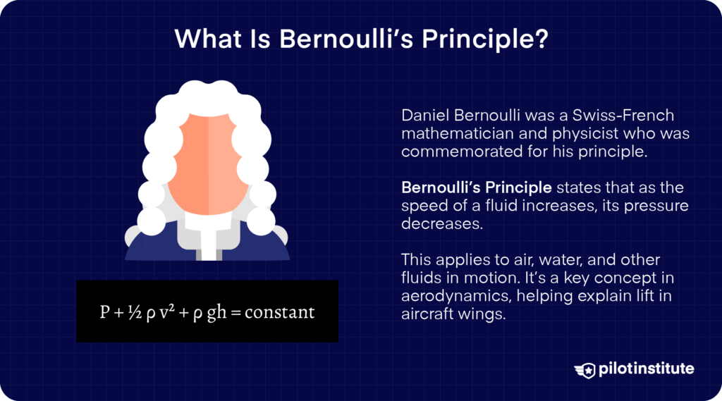
Simply put, Bernoulli’s principle states that whenever a moving fluid’s velocity increases, the pressure within it decreases.
But why does this happen?
Bernoulli’s principle is based on something called the conservation of energy.
Basically, the total energy in a closed system will always be constant. It’s possible to convert the type of energy in the system into a different type. However, there won’t be an overall increase or decrease in the total energy in the system.
Types of Pressure
You can think of the air surrounding a moving aircraft wing as a system. From the wing’s perspective, air is rushing towards it in a straight line at high velocity. When something has velocity, we can say it has kinetic energy, which translates to dynamic pressure.
We also know that air has pressure within it even when it’s not moving. This pressure mainly comes from the constant collisions between its molecules. This gives air particles pressure energy, which acts as static pressure.
So, the air in our system carries two types of pressure. Either can be converted into the other type, but as one type increases, the other will decrease. The total pressure or energy will remain constant.
In mathematical terms, Bernoulli’s equation looks like this:
P + ½ ρv2 = constant
In this equation,
- P represents the air’s static pressure.
- The combined term of ½ ρv2 represents the air’s dynamic pressure.
- ρ (pronounced rho) is the air density.
- v is the velocity of the moving air.
Here, we assume that the air doesn’t compress, isn’t viscous, and flows perfectly steadily. In reality, things are more complicated, but our simplified view is a reasonable model.
The Venturi Tube: A Classic Example
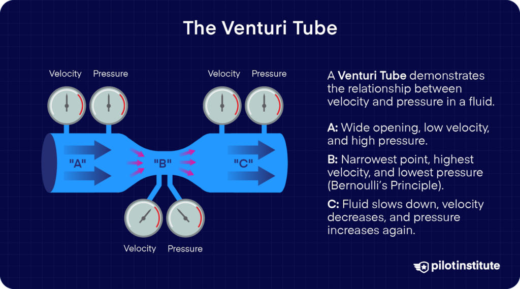
You can even see Bernoulli’s principle in action if you observe a venturi tube. A venturi tube is a straight tube with a wide opening followed by a narrow midsection. The end of the tube returns to the same wide diameter.
If you attach gauges measuring the pressure and velocity of a fluid flowing through the tube, you’ll see readings that match Bernoulli’s results.
The fluid moves slowly in the wide sections. Consequently, the static pressure reading at those points is high. As the tube narrows at the neck, the fluid is forced to accelerate. This increases its velocity at the cost of its static pressure.
How It Works
A fair question is, why does the fluid accelerate when the tube narrows?
The answer lies in something called the conservation of mass flow.
Basically, we have a fixed amount of fluid constantly entering the tube. This fluid has to exit the tube at the same flow rate since it has nowhere else to go.
Wide sections of the tube have enough room for a large quantity of fluid, so it doesn’t have to move fast in that section to maintain the flow rate.
When the tube narrows, the area available for the fluid to flow drastically reduces. The fluid has no choice but to move faster to make way for more fluid coming in from the wide opening.
Bernoulli’s Principle and Lift: How Wings Generate Lift
How Bernoulli’s Principle Relates to Flight
The relationship between a fluid’s static pressure and dynamic pressure is very useful for aircraft – especially their wings.
In steady, incompressible flow, static pressure tends to decrease as velocity increases, and vice versa.
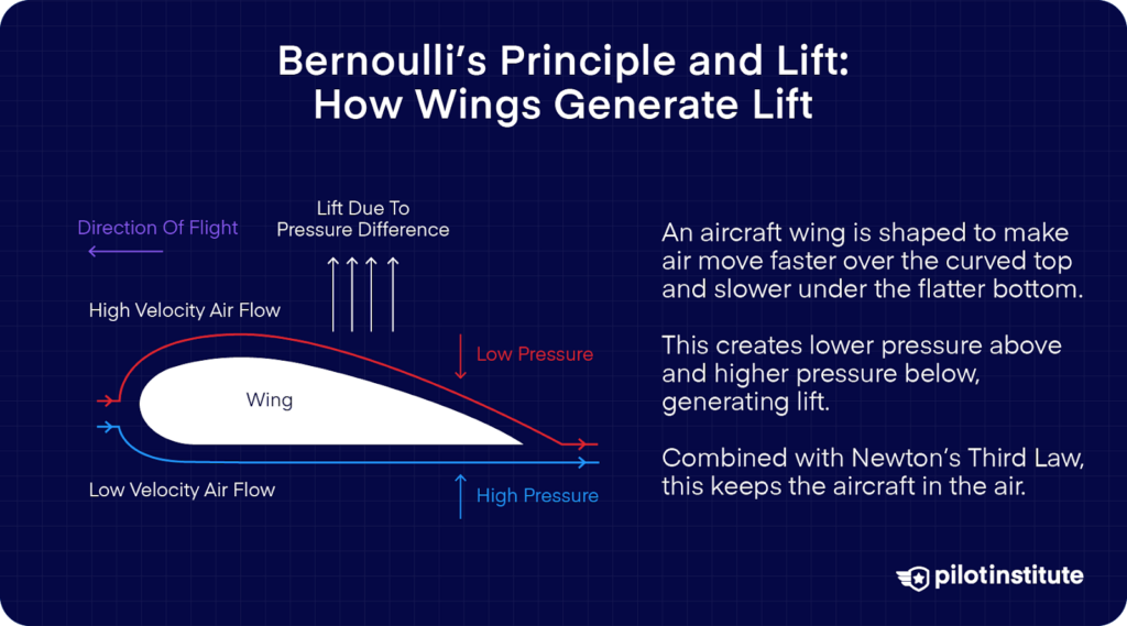
Wings are supposed to generate lift. To do so, they rely on a pressure differential between their top and bottom surfaces.
This means they have relatively lower static pressure on top and higher static pressure underneath.
Pressure Differences and Lift Generation
From Bernoulli’s principle, we know that increased flow velocity decreases static pressure. This means faster airflow over the top of the wing helps reduce the pressure above it.
As a fluid flows around a solid body, its velocity and pressure can change from one point to another.
By adjusting the body’s design (the shape of the wing), we can encourage these local pressure differences in the airflow to generate an overall force.
For a wing, this net force is what we call lift.
Flow Turning
So why does the air accelerate above the wing?
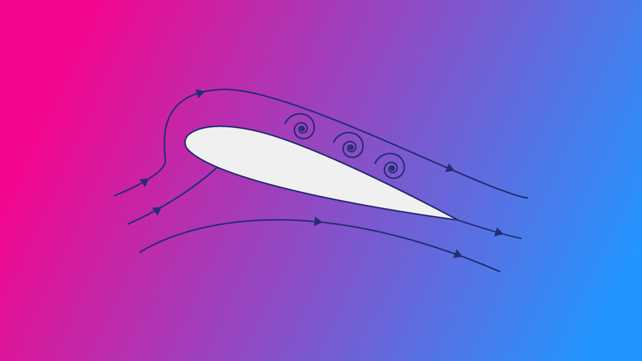
As the airflow approaches the wing, the flow splits above and below the leading edge. The air flowing above the wing tries to follow the wing’s curved shape.
The pressure difference between the leading edge and the upper surface curves the airflow towards the wing’s sloping surface. This change of direction, combined with the pressure gradient, accelerates the air over the wing.
What Affects Flow Turning?
We now know that the airflow above the wing needs to turn to accelerate. Two major factors affect how the airflow turns.
Wing Camber
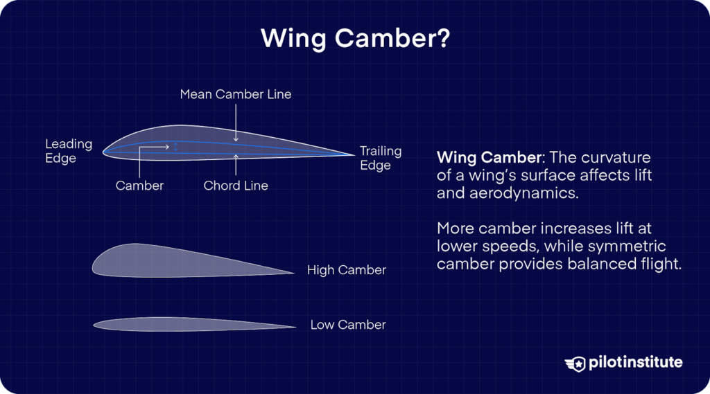
Wing camber defines how much more curved the wing’s upper surface is compared to the lower surface.
The greater the difference between the shape of the upper and lower surfaces, the larger the pressure difference between them. And as we know, a high pressure difference creates more lift.
Angle of Attack
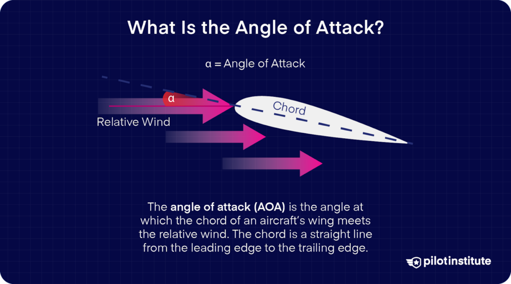
Angle of attack (AoA) is the angle between the airflow and the wing’s chord line.
The chord line is an imaginary straight line from the leading to the trailing edge.
If you tilt the aircraft’s wing so the leading edge is higher, the airflow will meet the wing at a steep angle. This means the airflow will have to turn a larger angle over the wing. Increased flow turning will increase lift.
Bernoulli’s Principle and Newton’s Third Law
Bernoulli’s principle does a good job of explaining the theory behind lift, but it doesn’t completely explain how the wing generates lift.
If lift were entirely due to Bernoulli, a symmetric airfoil (one with equal curvature on top and bottom) wouldn’t generate lift – yet it does when given the right angle of attack.
In reality, the wing also uses Newton’s third law to create lift. Newton’s third law is really simple. It states for every action, there’s an equal and opposite reaction.
How Does Newton’s Third Law Explain Lift?
How does this apply to the wing?
We explained earlier how the flow curves over the wing surface and deflects downward as it leaves the surface.
As the wing “pushes” the air downward through its shape and angle of attack, the air “pushes back” upward with an equal force. This reaction contributes to the overall lift.
This is why even a flat wing at an angle of attack can generate lift – it forces air downward.
Misconceptions About Lift
Unfortunately, it is very common to misinterpret Bernoulli’s principle and Newton’s third law while explaining lift. Here are the most common misconceptions.
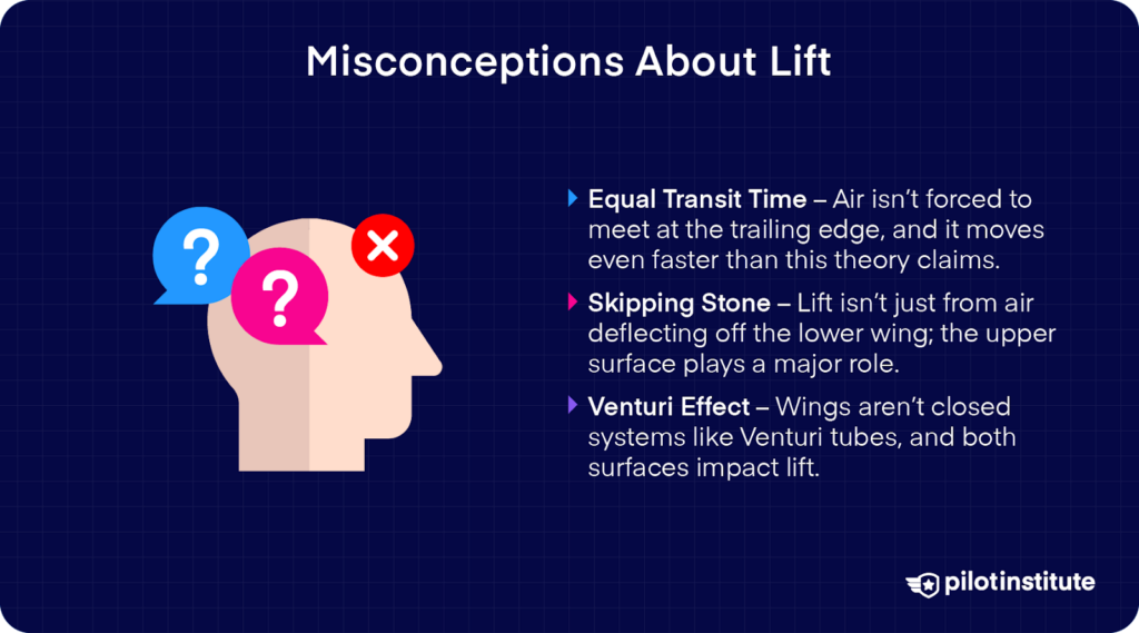
Equal Transit Time Theory
One incorrect theory is the “equal transit time theory.” This theory misleads people into believing that all aircraft wings have longer upper surfaces than lower surfaces.
The theory implies that air particles are somehow compelled to meet the same particle they separated from at the leading edge and ‘must’ increase their speed to catch up.
Why would air move faster simply because the upper surface is longer?
In reality, the airflow over the top surface moves even faster than this theory predicts. It also doesn’t explain why the air particle would even try to meet its old neighbor.
Skipping Stone Theory
This theory comes from oversimplifying Newton’s third law. This theory says airflow simply strikes the wing’s lower surface at an angle and deflects downward.
It suggests that the reaction force from this downward deflection alone is responsible for lift.
The problem with this theory is that it completely ignores the role of the wing’s upper surface in generating lift. If it were true, then the shape of the upper surface wouldn’t affect the airflow at all.
Real aircraft use wing spoilers that reduce lift by disrupting airflow above the wing. This proves lift generation has to involve the upper surface as well.
Venturi Theory
This theory incorrectly models the wing’s upper surface as ‘half a Venturi tube.’ It tries to relate how Bernoulli’s equation explains flow in Venturi tubes to the airflow above the wing
The problem with this idea is that a Venturi tube is a closed system with physical walls that force airflow to constrict. However, wings don’t have an upper boundary to restrict the airflow in this way.
Additionally, this theory completely ignores the flow under the wing. In reality, the lower surface also affects overall lift, meaning we can’t ignore its shape.
Practical Applications in Aviation

Carburetors in Piston Engines
The wing isn’t the only part of the aircraft that relies on Bernoulli’s equation. Carburetors in older aircraft, such as many Cessna 152s, use the same principle to function.
Carburetors use a venturi to accelerate air while lowering its pressure. This low pressure draws fuel from the fuel bowl into the airstream, mixing it with the air before entering the engine cylinders.
A problem with carburetors is that they are prone to icing – even in warm weather. This also happens due to the Venturi effect.
As air speeds up through the venturi, the pressure drop reduces its temperature. If the air is humid, the moisture can freeze, restricting airflow and reducing engine power.
That’s why carbureted aircraft engines have carb heat, which bypasses the venturi and introduces heated air to prevent or remove ice buildup.
Jet Engine Inlets
Jet engine inlets also rely on Bernoulli’s principle, although they use it differently than carburetors.
Instead of a narrowing passage that speeds up the flow, most subsonic inlets slow the air down and increase its pressure.
This still follows Bernoulli’s principle but in the opposite manner of a venturi.
Jet engines need stable, high-pressure airflow at the compressor face to operate efficiently. Without this input, the engine is vulnerable to a compressor stall.
Importance for Pilots and Engineers
How Do Pilots Use Bernoulli’s Principle?
Bernoulli’s principle isn’t something pilots think about routinely. However, grasping the concept does help them understand the basics of flight physics.
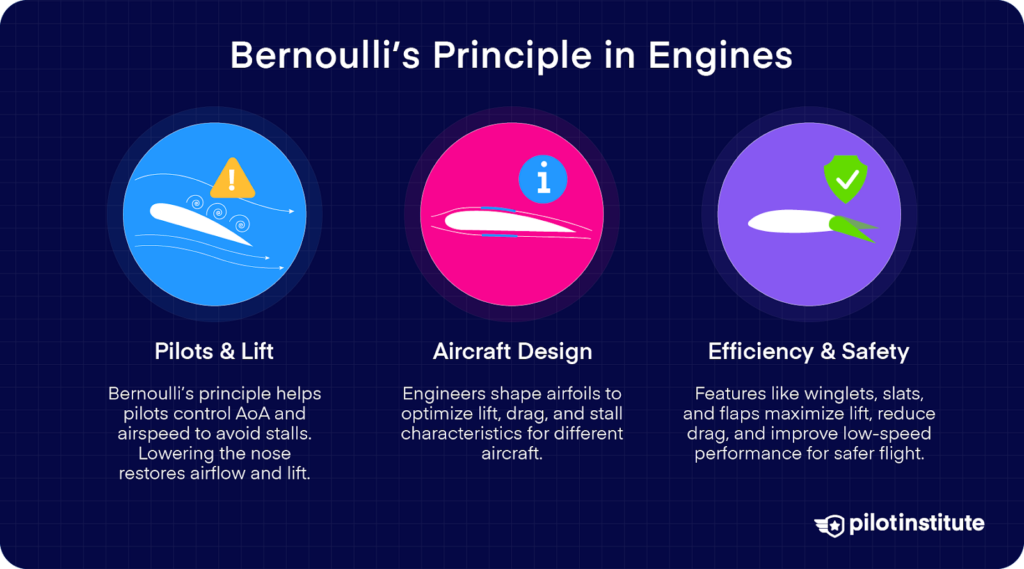
Pilots know their aircraft will stall if they exceed the critical angle of attack. Bernoulli’s principle helps them understand how the AoA affects the lift produced by the wing.
Bernoulli’s principle teaches pilots the importance of keeping airflow moving over the wing. This explains why they must maintain a certain minimum airspeed at all times.
Every pilot knows what to do if the aircraft stalls. Lower the nose! Pilots must reduce the AoA to restore smooth airflow over the wing if a wing stalls so Bernoulli’s effect can work properly again.
Impact on Aircraft Design
Aircraft manufacturers and engineers are keenly aware of Bernoulli’s principle.
Engineers use Bernoulli’s principle to shape airfoils to optimize the pressure difference needed for efficient lift generation.
They adjust wing camber, thickness, and aspect ratio to balance lift, drag, and stall characteristics for different aircraft roles. For example, this means designing high-lift wings for STOL aircraft rather than high-speed wings for jets.
Designing for Efficiency
While increasing airspeed boosts lift (per Bernoulli), it also increases drag. Engineers try to design wings that maximize lift while minimizing drag.
Features like winglets help manage airflow to reduce drag while preserving the pressure difference that generates lift.
Designing for Safety
Engineers design features that delay or manage airflow separation to maintain the Bernoulli effect and prevent abrupt stalls.
This includes leading-edge slats (to maintain high-speed airflow over the wing at high angles of attack) and stall strips (to ensure controlled stall progression).
Flaps and slats increase the airflow speed over the wing and enhance low-speed lift, allowing for safer takeoffs and landings.
These devices effectively increase the wing camber, boosting lift without requiring excessive airspeed.
Training and Education
Even though people have been building and flying aircraft for over a century, there’s still ongoing debate over how exactly the wing manages to generate lift.
Given the widespread incorrect theories about applying Bernoulli’s principle, you should take care not to develop misconceptions about this topic.
Use reliable sources like the FAA’s Pilot Handbook to learn about critical topics like this one.
NASA’s Glenn Research Center’s website also offers detailed explanations about aerodynamic concepts, including Bernoulli’s principle.
Conclusion
You now know how aircraft remain aloft by harnessing both Bernoulli’s principle and Newton’s third law.
With how complex pressure differences and deflected air combine to create lift, you can see just how hard it is to design aircraft wings.
That’s the real secret behind flight.