-
Key Takeaways
-
What Is the Chord Line in Aviation?
- The Difference Between a Chord Line and a Camber Line
- Types of Wings
-
The Chord Line and Angle of Attack
-
The Chord Line and Centre of Gravity
- A Small Note on Tapered Wings
-
Why Is The Chord Line Important?
-
Can Anything Change the Chord Line?
- Slats
- Flaps
- Ailerons
-
Conclusion
Airplane wings vary in shape and size, but all have standard features like the chord line. The chord line is a crucial datum point used to indicate the angle of attack relative to airflow. It’s an imaginary straight line from the wing’s trailing edge to the center of the leading edge.
The chord line is actually really important, especially when discussing aerodynamics. Here’s what you need to know!
Key Takeaways
- Chord Line: A straight line across the wing used for aerodynamic reference.
- Angle of Attack: Chord line helps measure and maintain a safe angle of attack.
- Center of Gravity: Used to calculate and balance the aircraft’s center of gravity.
- Wing Control: Flaps, slats, and ailerons change the chord line, impacting lift and control.
What Is the Chord Line in Aviation?
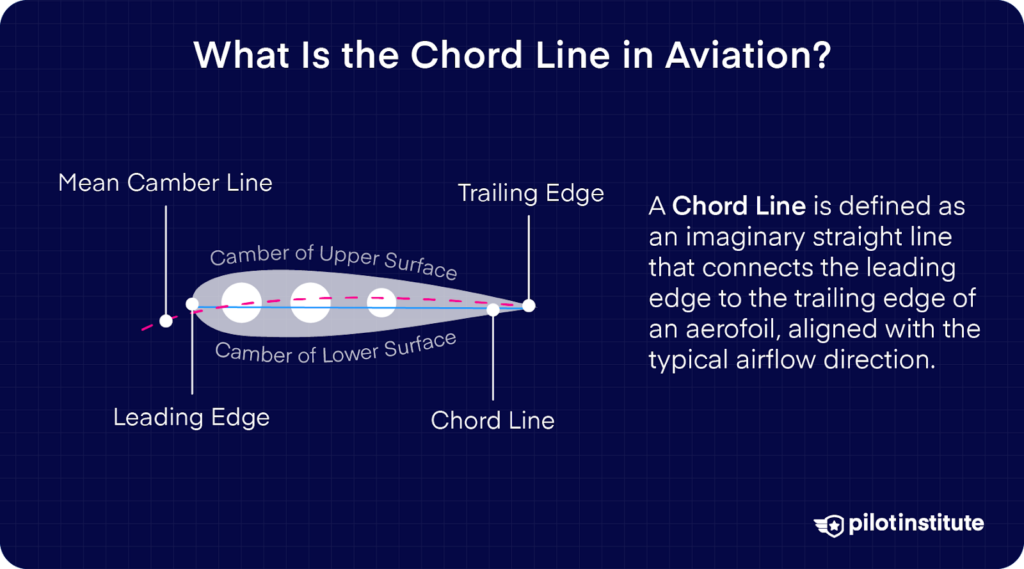
In general, the chord line is used as an easy-to-understand reference when referring to the properties of a wing or airfoil. It is a reference point for several aerodynamic and geometric calculations.
It is an imaginary, superimposed straight line that runs through the wing in cross-section, from the trailing edge to the wing’s leading edge.
Wait.
Why can’t we just refer to the wing “as is” without making imaginary lines? To answer this question we first need to understand the types of wings.
The Difference Between a Chord Line and a Camber Line
The chord line is a straight line that crosses the leading and trailing edges of the airfoil. The mean camber line is drawn halfway between the upper and lower surfaces.
Basically, the mean camber line is meant to indicate the midpoint between the top and bottom surfaces of the airfoil.
Types of Wings
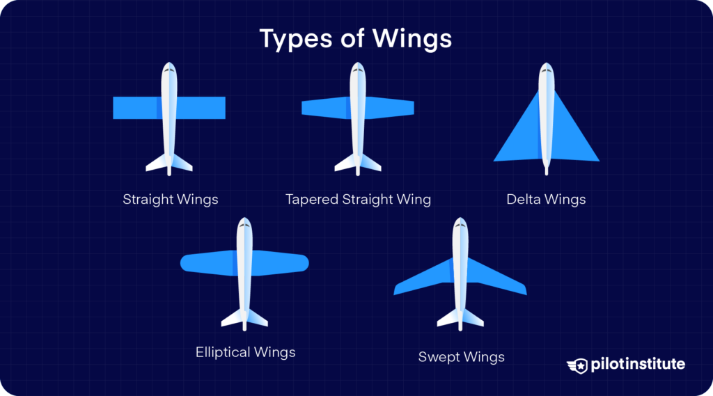
If you have seen more than one aircraft type, you will have noticed that their wings are different. There are many styles of the wing, including:
- Straight wings
- Swept wings
- Delta Wings
- Elliptical wings
- Tapered Straight Wing
These wings all generate lift. However, the diverse nature of their shape and behavior makes referring to a given point on ‘wings’ very difficult.
This issue aside, there is another reason why pilots, aircraft engineers, and designers talk about ‘chord lines’.
If you stand at the end of a wing (also called the ‘tip’) and look down the wing, you’ll see the upper surface has a curve (also called a ‘camber’).
And here’s the thing.
When was the last time you heard of anybody using a curved line as a reference point? Curved lines don’t make ideal datums to measure from, as they are not constant. This is especially true when discussing aerodynamics.
So, what’s the answer?
Chord lines, of course!
By creating a common convention and using this as a point of reference, regardless of the shape of the wing, we can all be sure that we are talking about the same thing.
A chord line allows us to create a constant in the simplest possible terms, from which aerodynamic and geometric calculations can be made.
Such as?
Well, read on as you are about to find out.
The Chord Line and Angle of Attack
If you’ve read our article on aircraft stalls, you’ll already appreciate how important the angle of attack is in continued (and safe) flight.
Here’s a quick recap.
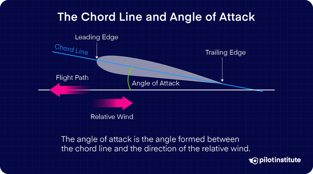
Simply put, the angle of attack is the angle at which the oncoming airflow meets the wing.
As a general rule, the greater the angle of attack, the more lift the wing produces.
So far, so good?
However, we have a little bit of an issue.
Measuring accurate angles, especially the angle of attack, from a curved surface (such as from an aircraft wing) can be challenging.
Here’s a simple explanation.
Imagine standing on a slope that gradually increases and decreases in steepness and being asked to point to whether the oncoming wind is coming from above or below you. Tricky, right?
It would be far easier if you stood on a flat and level surface.
This is exactly what the chord line is. A flat, consistent line that is easy to measure angles from.
The Chord Line and Centre of Gravity
The chord line provides another useful feature for aircraft designers, engineers, and pilots.
It all has to do with balance and aircraft behavior.
To understand how the chord line relates to the center of gravity, we need to delve briefly, into a little aerodynamic theory.
It goes something like this.
The airplane rotates and moves around several axes. These are:
- The Yaw Axis
- The Roll Axis
- The Pitch Axis
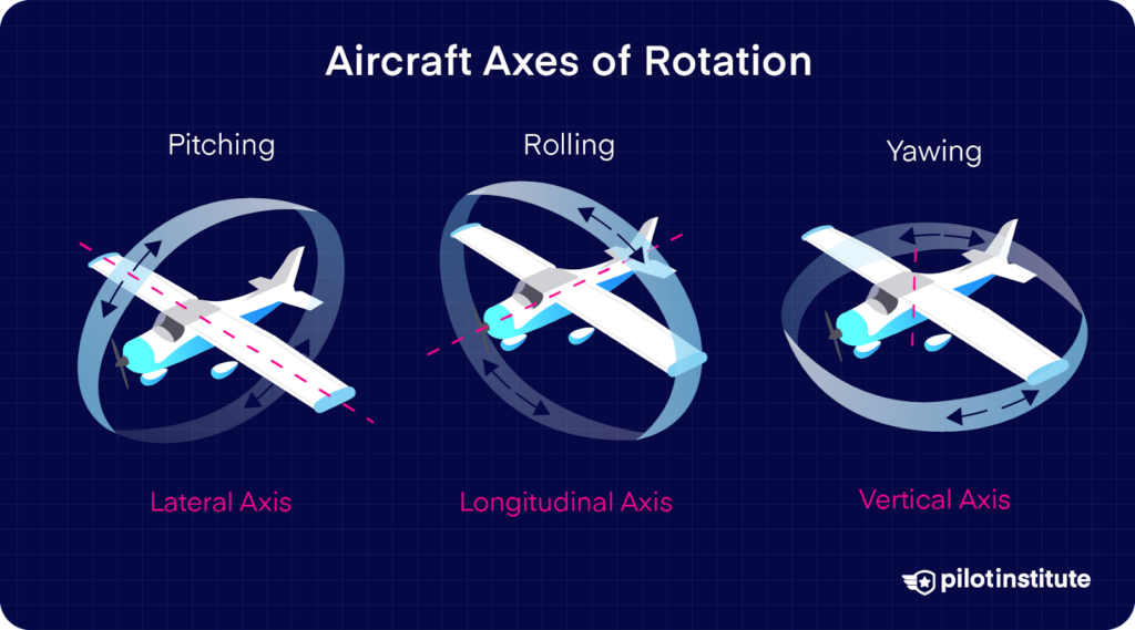
It is the last axis, the ‘pitch’ axis, that we are concerned about when discussing the chord line.
Imagine a see-saw. Where its pivot point is, is called the center of gravity. This is the singular point through which the combined weight of everything acts.
It is exactly the same with an aircraft, except we can’t actually see the pivot point. But trust us, it is there.
Does it make sense so far?
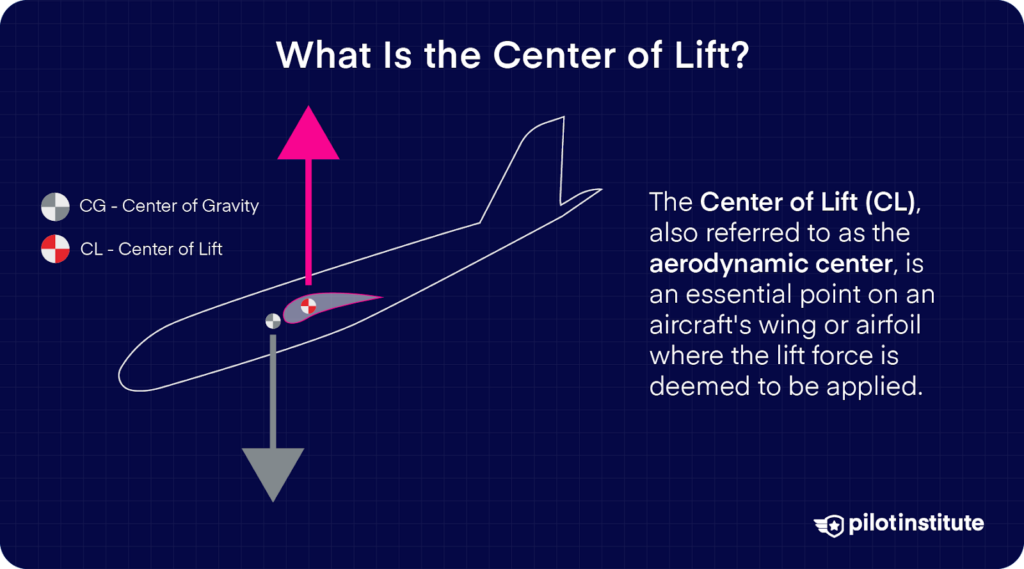
The wing also has a similar point, acting in the opposite direction… There is an area at a given point on the wing, between the leading edge and trailing edge, where the sum of all the lift forces act. This area is called the center of the lift.
Without getting too technical, and to keep it simple, three things can happen: –
- If the center of lift is forward of the center of gravity, the nose pitches up.
- If the center of lift is directly above the center of gravity, the pitch will remain unchanged.
- If the center of lift is behind the center of gravity, the nose pitches down.
It is safe to assume that if the center of lift changes position (the pulling force on top of the wing), or the center of gravity changes (the ‘pivot’ point of the aircraft), then one of the three above conditions will take place.
All pretty simple, right?
But how does this all relate to the chord line?
As you’d expect, the wing is constantly changing the amount of lift it produces due to variations in speed and angle of attack. In contrast, the center of gravity remains (roughly) in the same place.
The center of gravity, remaining relatively fixed, provides a great datum to calculate how a wing will behave concerning the movement of the center of lift.
All you need to do is specify where the center of gravity is located on the wing when viewed side-on in a cross-section.
Now, the eagle-eyed among you will have spotted a potential problem. All wings are different, with different curves, thicknesses, and widths. How could we possibly hope to talk about a fixed area with all these differences?
Easy, we use a chord line.
Regardless of the wing’s thickness, curvature or depth, we can draw our imaginary straight line straight through the leading edge to the trailing edge.
We’ve got a handy straight line to specify where the center of gravity is located along the wing.
We call it the “mean aerodynamic chord” or “MAC” for short. The center of gravity (also called CG) is expressed in terms of a percentage along this chord line.
The very frontmost point of the chord line is expressed as 0%. The rearmost point is expressed as 100%.
If your CG is 50%, you can expect to find the aircraft wing’s balance point around the middle of the wing.
You’ll often see airplane load sheets give reference to the CG as a percentage of MAC…
There’s one more thing you need to know…
A Small Note on Tapered Wings
Wings aren’t always rectangular. Sometimes, they are swept or tapered.
Luckily, we don’t have to work out the chord line for every point along the wing.
Avoiding too much technicality and using some clever math, the wing is measured at all points from front to back, and the average is taken from these points.
Again this gives you a chord line to reference both angles of attack and center of gravity.
Why Is The Chord Line Important?
The chord line and its position to the oncoming airflow are vital to understanding how much lift the wing can generate before it stalls.
If you aren’t consistent in where you take your measurement of the angle of attack, you can never truly know at what point the aircraft will stall!
The chord line, being flat, will allow us to accurately measure the oncoming airflow as the aircraft moves forward, meaning we can reliably predict the wing’s behavior.
Can Anything Change the Chord Line?
Wings are fixed and don’t change, right?
Nope, not quite.
There are a few things that will move and change the chord line. They are as follows:
Slats
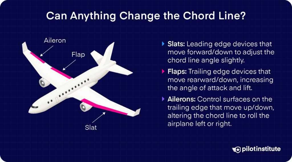
Slats are lifted augmentation devices fitted to the leading edge of the wing. When they are deployed, they move forward and, in some cases, down. This causes the angle of the chord line to change ever so slightly.
Flaps
Flaps have a massive effect on the chord line. As with slats, these are lifted augmentation devices, except in this case, they are fitted to the trailing edge of the wing.
When flaps are deployed, they move rearward and down. This causes the angle between the chord line and oncoming airflow (the angle of attack) to increase, creating more lift.
Ailerons
Ailerons are responsible for rolling the airplane. They move up and down and cause changes in the chord line and its position relative to the oncoming airflow.
This change contributes to the aircraft rolling either to the left or the right, depending on which direction the controls are manipulated.
Conclusion
While it might sound a little technical, the chord line is actually referenced to make life simpler. By talking about a straight line through the wing, we establish a consistent datum to reference the aerodynamic behavior of the wing.
If you find the thought of aerodynamics challenging, that’s okay! With our expert online guides, you can have the above concepts explained in plain and easy-to-understand terms. Why not check out our free Private Pilot Ground School online course and see how easy it can be?