-
Key Takeaways
-
What Is an Aileron?
-
How Do Ailerons Work?
-
What Is Aircraft Stability?
-
What Materials Are Used in Ailerons?
-
How Are Ailerons Actuated?
-
How To Make Ailerons More Effective
- Increasing The Deflection
- Increasing The Moment Arm
- Increasing The Aircraft Speed
-
What Is Aileron Flutter?
- How Is Aileron Flutter Reduced?
- Aileron Control In Stalls And Spins
-
The Problem With Outboard Ailerons
- Wing Divergence
- Control Reversal
-
What Are Inboard Ailerons?
- Why Use Inboard Ailerons?
-
What Is Adverse Yaw?
- How Should The Pilot Use The Rudder With The Aileron?
- Can You Turn The Aircraft Using The Ailerons Alone?
-
Modifying Ailerons To Reduce Adverse Yaw
- Differential Ailerons
- Frise Type Ailerons
-
Combined Controls
- Flaperons
- Spoilerons
- Elevons
- Coupled Rudder
-
What Is Aileron Trim?
-
How Does The Autopilot Control The Ailerons?
-
What Happens When the Aileron Fails?
- How Do Mechanically Actuated Ailerons Fail?
- How Do Hydraulically Actuated Ailerons Fail?
-
Countering Aileron Failure
-
Conclusion
At first glance, ailerons look like ordinary hinged panels on the wings, but don’t be fooled—they’re important for keeping an aircraft both stable and maneuverable.
These control surfaces dictate the aircraft’s roll, and this allows it to bank smoothly through turns or even recover from turbulence. But there’s much more to ailerons than just rolling left or right.
Have you ever wondered how pilots keep control at high speeds, during stalls, or even when systems fail? Or how do modern airplanes reduce dangerous effects like aileron flutter or adverse yaw?
From simple mechanical linkages in small aircraft to high-tech fly-by-wire systems in airliners, ailerons have evolved with aviation itself.
If you’re ready to uncover how these small panels shape the way aircraft fly and stay safe, dive in—this guide has everything you need to know.
Key Takeaways
- Ailerons control the aircraft’s roll by adjusting lift on each wing.
- They work by deflecting airflow at the wing’s trailing edge.
- Adverse yaw is a side effect of aileron use, countered by rudder input.
- Modern aircraft use various systems, like hydraulics and fly-by-wire, to control ailerons.
What Is an Aileron?
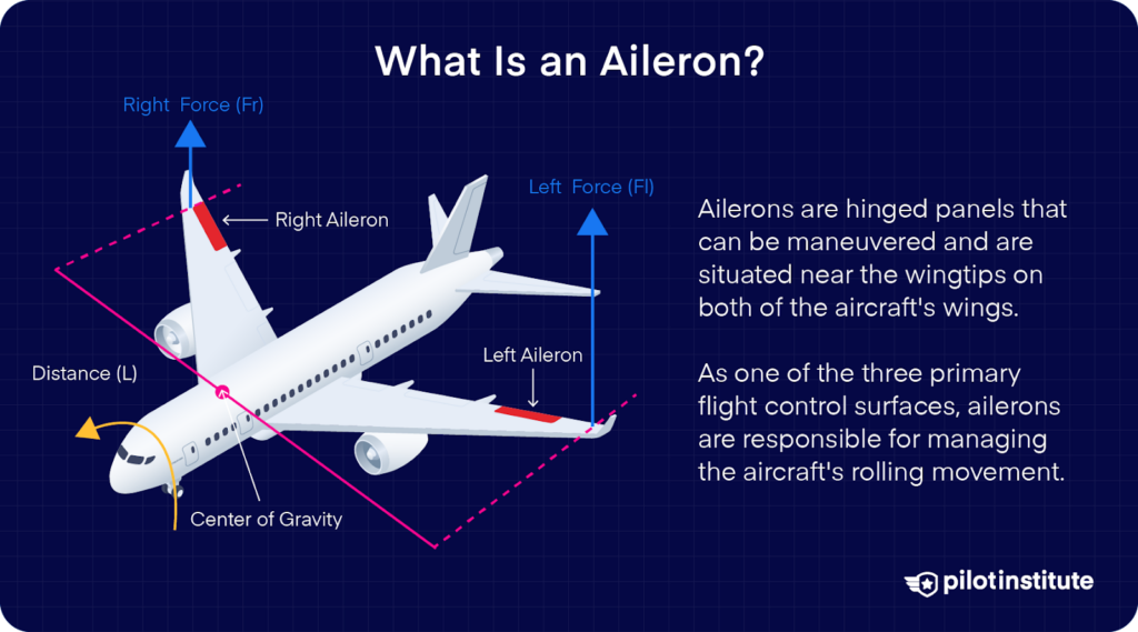
An aileron is a controllable hinged panel located close to the wingtip on each of the aircraft’s wings. Ailerons are one of the three primary flight control surfaces and are used to control the aircraft’s rolling motion.
Roll or bank is the aircraft’s movement about its longitudinal axis. The pilot is able to control the aircraft’s roll by turning the control yoke or sidestick in the cockpit. The ailerons are connected to the control yoke and can be moved by rotating the yoke left or right.
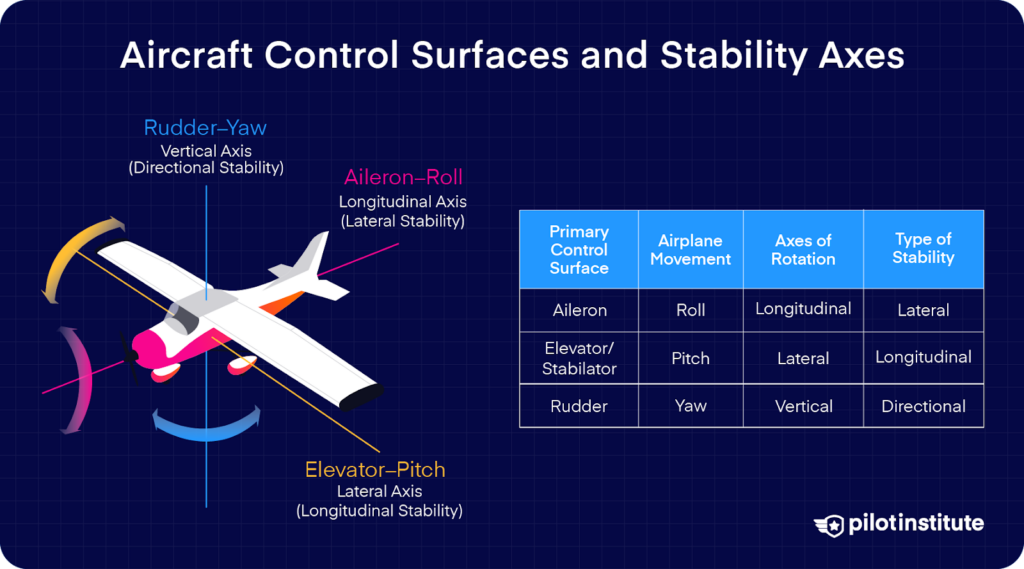
Moving the yoke towards the right makes the aileron on the right wing go up and the aileron on the left-wing move downwards simultaneously.
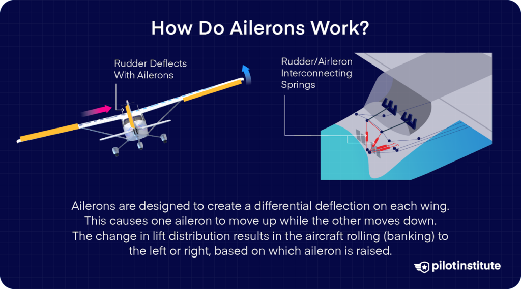
The opposite holds true when the yoke is turned to the left. Since they’re located on opposing sides of the longitudinal axis, both ailerons need to move in the opposite directions to complement each other’s motion.
How Do Ailerons Work?
The aircraft’s wing is able to generate lift due to its shape. The more the wing’s shape is able to change the direction of the flow of air over the surface, the more lift it will produce.
Why does this increase the lift?
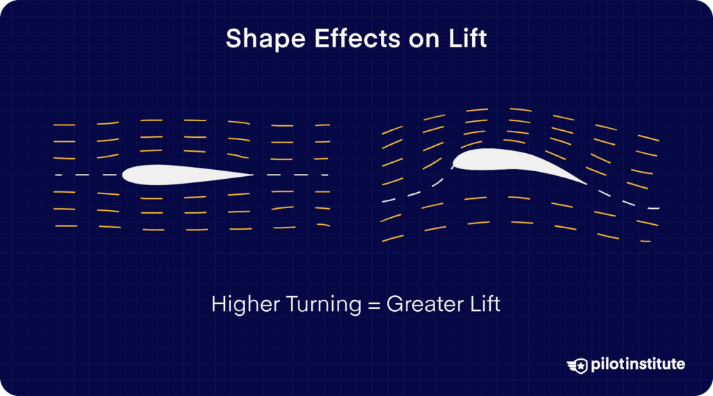
Lift requires the presence of a pressure differential between the airflow on the top and bottom surfaces of the wing. If the flow on both sides is symmetrical, the wing won’t produce any lift.
The diagram below shows how the airflow is affected by changing the shape of the wing’s trailing edge. The asymmetry between the top and bottom surface of the wing is called wing camber.
The lines represent the flow of air from left to right and are called streamlines. Notice how the airflow curves downwards in the diagram on the right. This downward deflection of the airflow leads to an increase in lift produced upwards.
Both wings are generating equal amounts of lift when the aircraft is flying straight and level. Moving an aileron changes the shape of the wing’s trailing edge, affecting the lift it is able to generate.
Decreasing the lift on one wing and simultaneously increasing it on the other results in one wing dropping downwards and the other upwards.
This movement turns the aircraft about the longitudinal axis, making it enter a bank. The downward movement of the aileron increases the asymmetry and, therefore, the camber while raising the aileron reduces the wing camber.
What Is Aircraft Stability?
Stability is the aircraft’s tendency to maintain its attitude or orientation. You want your aircraft to be reasonably stable but still controllable.
If the aircraft is too stable, it’ll be very reluctant to change its attitude and won’t be very responsive to the pilot’s control inputs. This type of aircraft will need large control surfaces capable of significant deflection angles.
On the other hand, excessively unstable aircraft are unsuitable for carrying passengers since they wouldn’t be very safe or comfortable. Unstable aircraft designs are better suited for high-maneuverability aircraft like aerobatic stunt airplanes or military fighters.
The ailerons produce a rolling motion that turns the aircraft about the longitudinal axis. This means that they have to be effective enough to counter the aircraft’s inherent lateral stability.
Lateral stability depends on the aircraft’s design. Factors such as the wing’s location, dihedral, and sweepback influence how much lateral stability the aircraft has.
What Materials Are Used in Ailerons?
In recent times, composite materials have been introduced for flight controls – even in small general aviation aircraft.
Aircraft such as the Cessna 400 use a combination of epoxy and carbon fiber to form flight control structures that are far lighter than previously used aluminum or steel alloys.
Reducing the aileron’s weight cuts down the force needed to actuate it and also lightens its support structures on the wing.
Composites are also stiffer, which reduces flutter in the aileron. All this comes at a cost, although recent advancements have reduced material and manufacturing expenses, allowing even small aircraft to use composite structures at a reasonable cost.
Large passenger aircraft had composite ailerons as early as the 1960s with the Lockheed L-1011. Nowadays, entire aircraft such as the Cirrus SR22 is built entirely using composites.
How Are Ailerons Actuated?
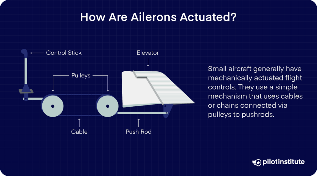
Small aircraft generally have mechanically actuated flight controls. They use a simple mechanism that uses cables or chains connected via pulleys to pushrods.
The diagram above shows the elevator linkage, but the ailerons are also connected in a similar manner. The linkages in the system contain control stops that limit control inputs and prevent the pilot from overstressing the airframe by making abrupt or extreme movements.
This system is fairly cheap and easy to maintain. Despite being first introduced as early as 1908, you can find mechanical controls in most small aircraft flying today.
You might be surprised to learn that tiny four-seater Cessna 172s and 140-passenger Boeing 707 airliners both use simple cables for moving the ailerons and elevators!
The drawback of simple mechanical systems is that all the aerodynamic forces experienced by the control surface get transmitted back to the pilot’s hands.
Aerodynamic forces increase in intensity the faster you fly. Pressure from the high-speed airflow acts against the controls, making them stiffer and requiring the pilot to exert more force on the controls.
Larger and heavier aircraft also require control force to overcome their inertia. The aforementioned Boeing 707 (weighing 68 tons!) was notorious for having very heavy controls.
To cope with the increasing control forces, aircraft manufacturers developed a hydraulic system that assisted the mechanical controls. The hydraulic system works similarly to a car’s power steering and greatly reduces the effort needed by the pilots.
Since the hydraulic fluid doesn’t compress, it simultaneously exerts pressure at all points along the line. This ensures perfect synchronization in flight control actuation.
Large aircraft use multiple hydraulic lines for redundancy, and some of them can still use the cable system as a last resort in case of complete hydraulic failure.
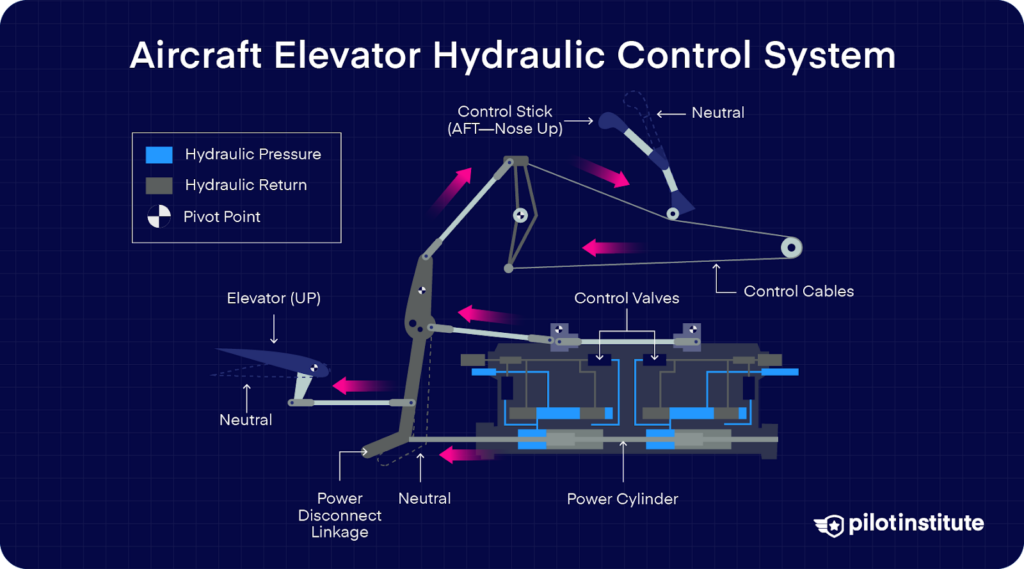
The most recent development in in-flight controls is the Fly-By-Wire system.
This system has no mechanical connection between the control stick and the flight controls at all. The pilot’s inputs are electronically sent to a computer, which commands a control surface movement using an electrical or hydraulic actuator.
Hydraulic actuators only work in one direction; they can force the aileron to move, but the aileron can’t drive the actuator from the aerodynamic force it experiences.
That’s why Fly-By-Wire aircraft have an ‘Artificial Feel’ system that provides pilots with feedback on the controls so they don’t enter control inputs that overstress the airframe. Fly-by-wire is expensive, so you won’t find it on most small general aviation aircraft.
How To Make Ailerons More Effective
Since it’s the airflow at the trailing edge that has the most significant effect on the lift, we know that the ailerons need to be placed along the wing’s trailing edge to maximize their effectiveness.
Next, the aircraft designer needs to figure out where to place the aileron along the wingspan.
The rotational force that’s needed to move an object about an axis is called torque. The simplest formula for torque is:
Torque = F x L
L is the distance between the object and the axis of rotation, also called the moment arm. In this case, L defines how far along the trailing edge of the wing the aileron is placed. The axis of rotation here is the aircraft’s longitudinal axis, which runs through the center of the fuselage.
F is the force that’s applied perpendicular to the moment arm. This force is the result of the airflow hitting the deflected aileron. When the aileron is in the downward position, the wind strikes it from below, producing an upward force, and vice versa.
Increasing The Deflection
If you want to increase the aircraft’s roll rate, you can either increase the force or the moment arm. The force can be increased by deflecting the aileron to a greater degree.
The problem is that the aileron can only be deflected to a point after which the drag becomes significant. You also run the risk of increasing the wing’s Angle of Attack past the critical angle, which would stall the wing.
Most aircraft only have aileron deflection limits of 20 to 25 degrees. For some perspective, flap extension angles go up to 40 degrees for most aircraft.
Increasing The Moment Arm
The other way to increase the moment of force is by increasing the moment arm. If the ailerons are placed near the wingtips, you’ll need minimal deflection to produce the torque required to roll the aircraft.
Increasing The Aircraft Speed
Small, light, and low-powered aircraft such as the Cessna 172 have a relatively narrow operational speed range ranging from 40 knots up to about 160 knots. Commercial airliners fly at speeds above 300 knots but also need to be controllable at speeds below 150 knots.
Flight controls become more responsive but also more sensitive as the aircraft speeds up. Since the ailerons work by manipulating airflow, it makes sense that a large volume of air flowing at high speed would only need to be deflected by a small angle to generate a significant banking force.
The high sensitivity of ailerons near the wingtips could lead to a loss of control during high-speed flight if the pilots aren’t gentle on the controls.
What Is Aileron Flutter?
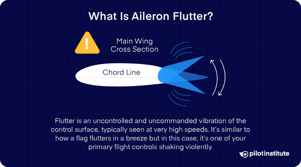
While you can increase aileron sensitivity by flying faster, flying too fast will induce something called flutter in the aileron. Flutter is an uncontrolled and uncommanded vibration of the control surface, typically seen at very high speeds.
It’s similar to how a flag flutters in a breeze, but in this case, it’s one of your primary flight controls shaking violently. Unlike the elevators and rudder mounted close to the fuselage, the ailerons’ location at the end of the long, thin, and flexible wings makes them much more prone to flutter.
The ailerons are only able to withstand flutter for a limited amount of time before the oscillations damage the wing or detach the aileron completely.
Flutter isn’t limited to high-performance aircraft, it can even show up in a slow and humble Cessna 152!
The most common reason for flutter in the ailerons is due to low tension in the aileron cables. Excessive free play in the controls means that the aileron is at the mercy of aerodynamic forces, and will move about without the knowledge or control of the pilot.
Other reasons for flutter include weak connections between the aileron and the wing, either due to missing bushings or misaligned brackets.
If your aircraft encounters aileron flutter, the first thing to do is to reduce your airspeed. The next step is to try to land as soon as feasible. Flying around for an extended period of time with flutter in the control surfaces will only increase the flutter as the wing and aileron connections deteriorate due to stress and fatigue.
How Is Aileron Flutter Reduced?
The problem is solved by adding a mass to dampen the oscillations, softening their amplitude, or even preventing them entirely.
Since ailerons are located at the wing’s trailing edge, the hinge connecting the aileron to the wing is located near the front of the aileron. Most of the aileron’s mass lies behind the hinge, making it tail-heavy.
Tail-heavy ailerons droop downwards when they aren’t being pulled by the control system. This makes the aileron more prone to flutter and can also induce buffeting. Aircraft manufacturers balance ailerons by adding weight forward to the hinge. This shifts the aileron’s Center of Gravity (C.G.) forward.
With enough mass added, the C.G. will shift until it’s exactly aligned with the axis of the hinge. Equal forces about the hinge result in the aileron staying neutral when left alone. This is called having a balanced aileron.
Adding even more weight will lead to the control surface being overbalanced, which means the aileron will try to move upwards in the absence of control inputs. Aircraft designers try to use as little mass as necessary since any excess weight will make the controls heavier and more difficult to operate.
One of the dangers of overbalancing the ailerons is that it can allow the ailerons to ‘lock’ when deflected at a high angle. The aileron moves to a greater angle than commanded by the pilot and stays there. Considerable force is needed to break the aileron lock.
The presence of contaminants like mud or ice sticking to the aileron will also affect its C.G., potentially reverting the aileron back into a tail-heavy state. That’s why you need to make sure your control surfaces are free of contaminants during your pre-flight walkaround.
Aileron Control In Stalls And Spins
A wing stalls when the airflow approaches it at an angle greater than the Critical Angle of Attack. The resulting loss of lift leads to a rapid descent by the aircraft. If the loss of lift is uneven between both wings, it’s possible for only one wing to stall. This is called having a wing drop. It’s one of the most common causes of a stall turning into a spin.
Aircraft wings have a clever design feature built into them by designers. The entire wing is twisted along its length to adjust the distribution of the lift that it generates. Twisting the wing changes its Angle of Incidence, which affects the effective Angle of Attack of each part of the wingspan.
A wing twist that causes a greater angle of incidence at the root than at the tip is called washout and is the most common type of wing design.
Wings with a washout design generate most of their lift in the area near the wing root, gradually decreasing the amount of lift towards the wingtip.
Why would you not want a lift to be distributed evenly across the whole wing?
Washout is actually a safety feature. It is designed to allow the pilots to retain aileron control as the wing stalls.
The greater Angle of Incidence of the wing at the root means that that section of the wing has a higher effective Angle of Attack.
This area will reach the Critical Angle of Attack first and will stall even as the outer parts of the wing are still generating lift. And what’s on the outer parts of the wings? Ailerons!
As the wingtip hasn’t yet stalled, the ailerons will still retain some measure of effectiveness. The pilot will be able to use them to level the wings and avoid worsening the stall.
If the wings aren’t level, the lift requirement increases dramatically due to the presence of centrifugal force. This only widens the gap between the amount of lift that’s being generated by the wings and what’s needed to overcome the stall.
Note that if the entire wing does manage to enter a fully developed stall, the pilot should stop using the ailerons entirely and just let them loose in the neutral position. Manipulating the ailerons to correct a dropping wing is likely to have the opposite effect and is likely to induce a spin.
The Problem With Outboard Ailerons
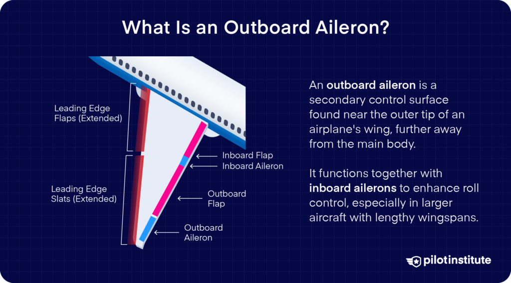
Similar to the aileron, the aircraft wing is also a long and thin structure. Just as the aileron is connected to the wing from one end, the wing itself also acts as a cantilevered beam by only being connected to the fuselage from one end. This makes the wing prone to flutter as well.
Aircraft wings are made out of aluminum or composites which are reasonably but not perfectly stiff. This causes Aeroelasticity; the wing bending due to the aerodynamic loads imposed on it. If the outboard ailerons are used when the aircraft is flying at high speeds, they can generate forces that could damage the wing and even break it off.
Wing Divergence
Every time the ailerons are deflected, the force from the deflection is transmitted to the wing through the aileron’s hinges. The wing, in turn, exerts a force on the fuselage as it tries to bend as it’s pushed by the force from the aileron. Inflexible wings are brittle and will snap much more readily.
Flexible wings dissipate the force from the aileron throughout the wing. A large amount of torque from the outboard ailerons increases wing divergence and heightens the possibility of the loads exceeding the wing’s torsional rigidity.
Control Reversal
At high airspeeds, the aileron may deflect so much airflow that the generated force can bend the wing itself instead of banking the aircraft.
The wing twists in the opposite direction of the aileron deflection. The resulting net deflection of the air leaving the twisted wing produces a roll in the opposite direction commanded by the pilot. This is called control reversal and it’s one of a host of phenomena that aircraft experience at high speeds.
Keep in mind that we’re talking about the wing twisting here, not bending. All aircraft’s wings flex, and in some aircraft like the Boeing 787, the wing flex raises the wingtips even higher than the top of the fuselage.
What Are Inboard Ailerons?
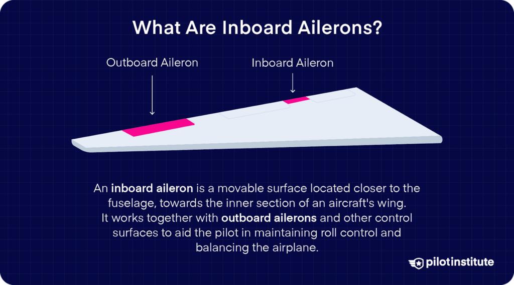
One way aircraft manufacturers reduce the aileron’s stress on the wing at high speeds is by installing a second set of ailerons on the wing positioned closer to the fuselage. These are called inboard or high-speed ailerons.
The inboard aileron’s small moment arm means that it won’t be able to produce much force to bank the aircraft, but that’s okay since aircraft don’t need to maneuver at high bank angles during high-speed flight.
Interestingly, Airbus does not equip most of its aircraft with inboard ailerons, not even the A380. That’s because all of the aircraft developed by Airbus operate using Fly-By-Wire. All flight controls are actuated electronically, and there’s no physical link between the control sidesticks in the cockpit and the flight surfaces.
The electronic actuation is governed by a flight computer, which is able to move the ailerons very precisely. This allows the aircraft to be controlled using only the outboard ailerons at all stages of flight, making inboard ailerons redundant.
There’s also no chance of an inadvertent movement of the sidestick jostling the sensitive ailerons since the computer disregards control commands that it thinks are unsafe.
Why Use Inboard Ailerons?
Inboard ailerons solve multiple problems simultaneously. Their most significant contribution is that they allow roll control at high speeds without bending the wing excessively.
This reduces the need for strengthening the wing structure, allowing the aircraft manufacturers to reduce the aircraft’s weight by making the wings and their support structures lighter.
Chances of control reversal are also reduced when the ailerons are placed closer to the fuselage.
Outboard ailerons exert forces on the wing behind its flexural axis, the point about which it twists. Downward-moving ailerons are supposed to raise the wing upwards, but excessive forces applied by the outboard aileron twist the wing downwards instead. The inboard ailerons apply their forces ahead of the flexural axis, reducing wing twists and control reversal.
Finally, if your aircraft has inboard ailerons, you don’t need expensive Fly-By-Wire systems for precise control. The outboard ailerons and some of the outer roll spoilers are locked out at high speed since the inboard ailerons are effective enough to maneuver the aircraft.
What Is Adverse Yaw?
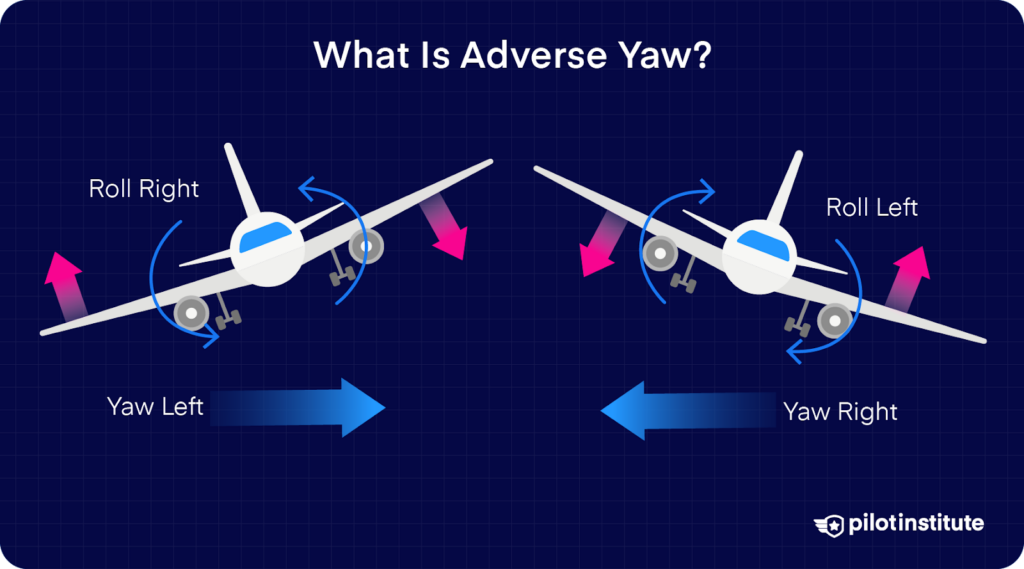
A side effect of using the ailerons for roll control is that they also make the aircraft swing about the vertical axis. This phenomenon is called adverse yaw.
Adverse yaw is created due to the drag differential between the two sides of the aircraft. The downward moving aileron produces more lift, but also generates more induced drag. The upward moving aileron has the opposite effect. The wing experiencing greater drag is forced backward, swinging the aircraft around in that direction.
Yaw could potentially be very helpful since we are trying to turn the aircraft when we roll it into a bank. But if you’re keeping track of the situation correctly, you’ll realize that the yawing motion is generated in the opposite direction from which we’re trying to turn the aircraft.
Have a look at the diagram below. Lowering the right aileron means we want that wing to move upward and the aircraft to the bank to the left, but the adverse yaw is trying to turn the aircraft to the right.
This is where the rudder comes in. A common misconception is that aircraft use their rudder to change heading, just like ships do. In fact, the pilot mostly uses the rudder to counter adverse yaw.
The pilot needs to add a touch of the inside rudder at the start of the turn and apply the outside rudder when coming out of the turn.
No aileron input, and therefore rudder input, is required once the bank has been established as long as the aircraft is making a shallow or medium turn.
Why is no aileron input required after the aircraft is established in the turn?
New pilots often believe that they need to keep applying force on the control wheel throughout the turn, possibly because they’re relating it to a car’s steering wheel.
The principle to keep in mind here is that lift doesn’t always act against the aircraft’s weight; it’s always acting along the vertical axis of the aircraft.
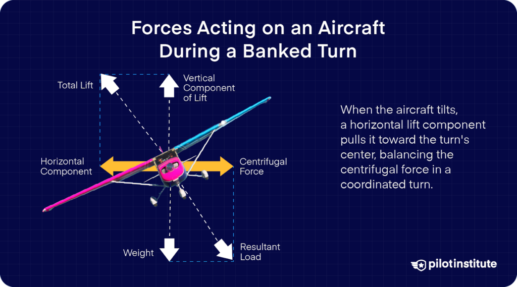
If the aircraft is tilted, the lift will develop a horizontal component pointed towards the center of the turning circle. This horizontal component of the lift keeps the aircraft in the turn and is balanced out by the centrifugal force when in a coordinated turn.
How Should The Pilot Use The Rudder With The Aileron?
The aircraft will enter a bank as commanded by the pilot via the ailerons, but the aircraft’s nose will get pushed out of the turning circle by the yaw if the pilot does not correct the rudder.
This will lead to a slipping turn with the aircraft flying in an uncoordinated manner. The turn coordinator’s slip indicator on the instrument panel will show the ball moving toward the inside of the turning circle, indicating the need for applying the inside rudder.
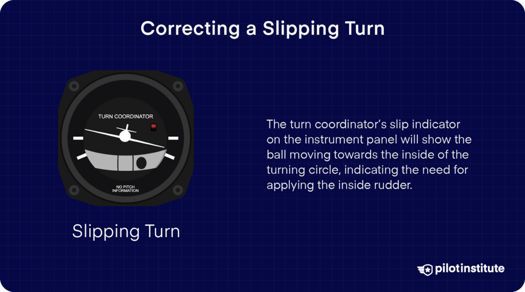
If you don’t use an outside rudder when returning to level flight, the ball moves out, and the aircraft skids in the turn.
Flying uncoordinated creates extra drag and the yaw produces a messy turn that your passengers probably won’t appreciate.
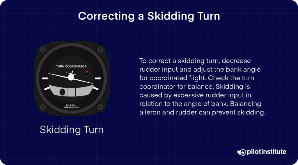
A fully coordinated turn involves all three primary flight controls. You’ll also need some elevator input if you want to maintain altitude while turning.
When the aircraft is flying in a bank, some of the lift transfers from the vertical to the horizontal component. Upward elevator input compensates by raising the nose slightly. Steeper turns will need larger elevator deflections.
Can You Turn The Aircraft Using The Ailerons Alone?
Some aircraft, such as the Cessna 152, are quite forgiving. If you don’t use the rudder at all, the aircraft will clumsily turn to your desired heading with an uncoordinated turn. But if the aircraft suffers from greater adverse yaw due to its design, it might not be able to turn at all.
The aircraft will bank when you command it using the ailerons, but won’t change its heading. Adverse yaw is more noticeable in aircraft with long wingspans. It’s also more pronounced when the aircraft is flying at a low airspeed.
Which type of aircraft comes to mind when you combine low speed and a long wingspan?
Gliders!
Glider pilots are intimately aware of adverse yaw and its effect on the aircraft during turns. When the aircraft is flying at a low speed, the airflow over the control surfaces is reduced.
This requires the pilot to make large aileron deflections to maneuver the aircraft. Large aileron deflections, in turn, produce more adverse yaw, which calls for more rudder input.
The rudder is also less effective at low speeds, further increasing the rudder input needed. This is why gliders are designed with large ailerons, allowing the pilot to minimize the required deflection and the ensuing adverse yaw.
Modifying Ailerons To Reduce Adverse Yaw
Aircraft designers use various strategies for adapting the ailerons to help pilots overcome adverse yaw. The easiest way to reduce adverse yaw is to decrease aileron deflection.
As you’ve learned above, we can reduce the required deflection by increasing the size of the aileron or its distance from the fuselage, but we’re still constrained by the available space and the length of the wing. Aircraft designers have had to come up with modified aileron designs to counter adverse yaw.
Differential Ailerons
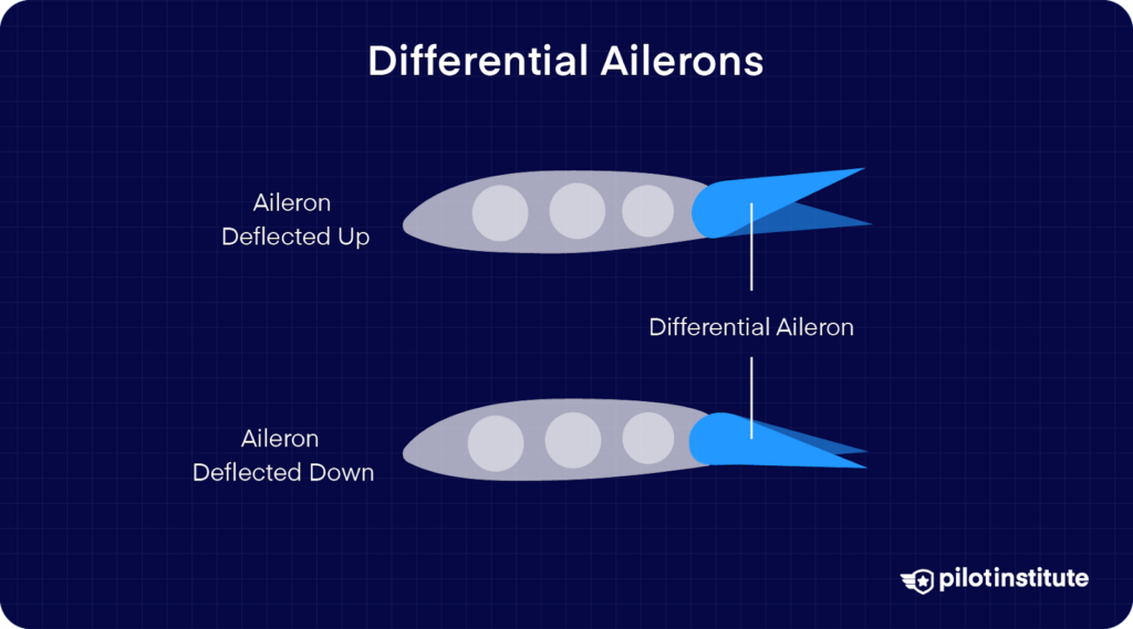
Adverse yaw comes from the increased drag on the downward-going aileron, so it makes sense to counter it by increasing the drag on the upward-moving aileron too.
Differential ailerons do just that by increasing the upward-moving aileron’s travel relative to the downward-moving aileron.
When you rotate the yoke clockwise to the limit in a Cessna 172, for example, the left aileron deflects 14 degrees downward.
At the same time, the right aileron moves 20 degrees upward. Differential ailerons are effective in reducing adverse yaw but can’t eliminate it entirely.
Frise Type Ailerons
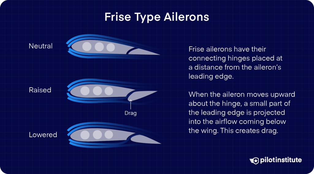
Frise ailerons have their connecting hinges placed at a distance from the aileron’s leading edge.
When the aileron moves upward about the hinge, a small part of the leading edge is projected into the airflow coming below the wing. This creates drag.
Note that we’re not talking about induced drag here. We’re talking about form drag, produced as the airflow strikes the exposed leading edge of the aileron.
Frise ailerons use form drag to counter the induced drag produced by the downward-moving aileron on the other wing.
An additional benefit of this type of aileron design is that it allows space for a slot in between the wing and the aileron. Air moves in through this slot and turns smoothly to follow the aileron’s contour.
The smoother airflow improves the aileron’s effectiveness at High Angles of Attack.
Frise-type ailerons can also be designed to operate like differential ailerons, further reducing but not completely eliminating adverse yaw.
Combined Controls
Real estate on the wing is precious. Most aircraft combine the functions of different flight control surfaces to maximize the roll authority available to the pilot.
Besides the ailerons, other flight controls located on the wing include flaps on the inboard trailing edge and flight spoilers on the upper surface.
Flaps lower to provide extra lift to the aircraft, allowing it to fly slower without stalling.
Spoilers drastically reduce lift by disrupting airflow over the wing. When their movements are synchronized with the ailerons, the ensuing extra torque reduces the demand on the ailerons.
The disadvantage of combining flight controls is that if there’s a failure, you have to deal with the loss of two flight controls instead of one.
Flaperons
While they are essential during takeoff and landing, flaps aren’t used at all during cruise flights. On the other hand, you don’t want the outboard aileron operating during the cruise, for reasons explained previously.
Combining the flap and inboard aileron optimizes the space on the trailing edge and saves weight since only one assembly and control system is needed.
What’s the difference between an inboard aileron and a flaperon?
If a panel moves in sync with the ailerons but doesn’t droop downwards when the pilot lowers the flaps, that panel is called an inboard aileron.
If it does move downward with the flaps, it’s a flaperon. The flaperon’s control system includes a mixer that combines separate pilot inputs for flaps and aileron.
We don’t want the airflow departing the wing’s trailing edge to get disturbed due to the flaperon so its upward movement is kept limited and it doesn’t deflect upwards as much as the outboard aileron does.
The panel itself is also mounted clear of the trailing edge to prevent the downwash from disturbing the airflow and striking the control surface.
Spoilerons
Large aircraft are usually equipped with spoilers, which are control surfaces located on the top of the wing. These panels extend out into the airflow to create drag and slow the aircraft down.
If you only extend spoilers on one wing, the drag imbalance produces a turning force just like the ailerons do.
The spoilers on the downgoing wing are raised, while the panels on the other wing remain flush with the surface. Spoiler panels that are designed to operate in this manner are called spoilerons.
Most large aircraft use spoilerons in conjunction with ailerons to improve roll authority.
Spoilerons are placed at some distance from the trailing edge so they aren’t as vulnerable to control reversal.
In fact, some aircraft such as the Boeing B-52 or the Mitsubishi MU-2 don’t have any pure ailerons at all! Their entire roll control comes from spoilerons because the aircraft’s wing was prone to control reversal due to its flexibility.
Since they can only move upward, they are only able to reduce the wing’s angle of attack.
The lifting wing sees no action from the spoilerons, so if it’s already close to the critical angle of attack, they won’t push it over the limit.
Another benefit of using spoilerons is that they don’t produce adverse yaw. Spoilerons only generate drag on the downgoing wing, pushing it backward and producing a yawing motion that helps the aircraft turn.
The downside of using spoilerons exclusively is that they aren’t as effective as pure ailerons. That’s why the B-52 has very poor roll control, especially at slow speeds.
Elevons
An elevon is the combination of the elevator and the aileron into a single control surface. This type of design is common in delta-winged aircraft such as fighter jets. The most famous civilian example is the Concorde, which featured a set of outboard, middle, and inboard elevons.
When panels on both wings move in the same direction, they act as the elevator. When they move in opposite directions, they create the lift differential you’re familiar with and make the aircraft rotate.
Delta winged aircraft spend most of their time at high speed, so they have ample airflow over the control surfaces to allow the controls to be effective. Elevons make the pilot’s life harder when the aircraft slows down.
The controls are limited by the fact that they need to perform two functions that may ask them to work against each other.
For example, if the pilot wants to perform a climbing turn to the right, the right elevon would move up if it were acting as an elevator but would move downwards if it were acting as an aileron to bank the aircraft to the right.
Coupled Rudder
Since you have to use the rudder every time you operate the ailerons, why not automate rudder deflection?
The rudder and ailerons can be linked using interconnect springs, as shown in the diagram.
Some degree of rudder input gets applied simultaneously as the pilot moves the control yoke to apply aileron input. The mechanism can be overridden by the pilot to allow the aircraft to enter a slip or to counter gusts.
A more sophisticated system is found in modern aircraft and is called the Yaw Damper. Yaw Dampers are primarily used to counter instability and Dutch Roll tendencies in aircraft with swept wings but are also effective against adverse yaw.
Pilots don’t need to touch the rudder at all while making turns since the yaw damper eliminates adverse yaw entirely.
Yaw dampers are turned off at landing and takeoff so that the pilot is able to positively identify a malfunctioning engine.
If the yaw damper is still active when an engine fails on takeoff or landing, it’ll automatically compensate for the yaw caused by the engine’s lack of thrust.
What Is Aileron Trim?
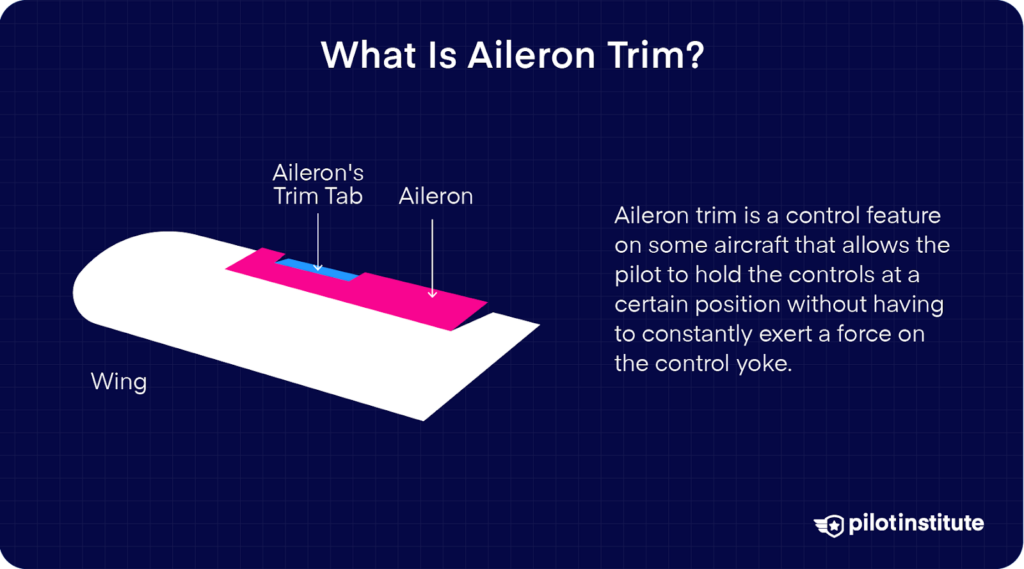
Flight control trim is a system that allows the pilot to hold the controls at a certain position without having to constantly exert a force on the control yoke. All three flight controls have independent trim systems, although it’s common for small aircraft to not be equipped with rudder or aileron trim.
Among the three controls, the elevator trim is the most frequently used trim by the pilot. Aileron and rudder trim can be convenient for the pilot, but aircraft manufacturers design their aircraft to be generally stable in the lateral and directional axes.
Basically, the aircraft should generally fly straight if the pilot leaves it to its own devices since there shouldn’t be any net force pulling the aircraft in either direction.
The amount of time the aircraft spends in a turn throughout the flight is usually small enough for the pilot to get by without having aileron and rudder trim installed.
When would you need aileron trim?
As the airframe gets older, the aircraft might develop a tendency to turn in one direction without being commanded by the pilot.
Uneven wear and tear or damage from accidents such as bird strikes or hard landings will eventually take their toll on the fuselage, with one side experiencing slightly more drag than the other.
Aileron trim can be used to relieve the pilot from continuously turning the yoke throughout the flight.
The pilot would also appreciate having aileron trim available if the weight of the passengers and cargo is loaded unevenly between the two sides of the fuselage or if the aircraft draws fuel unevenly from the fuel tanks.
These aren’t particularly critical use cases, as they are all easily correctable with small aileron movements made by the pilot at regular intervals. Aileron trim serves more as a convenience to the pilots by reducing their workload.
Most small aircraft aren’t equipped with aileron trim at all. Those that do have it either move the aileron itself or manipulate a small moveable panel on the aileron called a trim tab.
How Does The Autopilot Control The Ailerons?
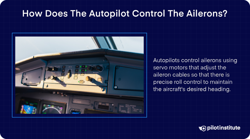
Most basic autopilots are single-axis units. This means that they are only able to control one of the aircraft’s primary controls and therefore can only move the airplane about a single axis.
The most common single-axis autopilots control the ailerons only. The autopilot uses a servo to move one of the ailerons or their trim tabs.
The simplest use for a single-axis autopilot is to act as a Wing Leveler. The computer takes input from the aircraft’s turn coordinator and uses the roll servo to apply aileron input until the turn coordinator shows the wings level.
This might seem too simplistic to be a useful feature, but it is commonly used to prevent pilot fatigue in gusty conditions. The Wing Leveler is also useful in low visibility conditions, where human pilots are prone to the effects of vertigo.
Wing Leveler autopilots have no idea what the aircraft’s intended heading is. They just keep the wings level, and the aircraft will simply drift with the wind if it’s experiencing any significant crosswind.
Full single-axis autopilots receive inputs from the aircraft’s Directional Gyroscope and are able to maneuver the aircraft to turn to and maintain a heading. The elevator and rudder control are left to the pilot.
Advanced autopilot systems use the ailerons in conjunction with the other flight controls using more inputs from aircraft instruments and can even manipulate engine power.
These systems can be highly complex and accordingly have exorbitant price tags.
What Happens When the Aileron Fails?

Given the vital role of the aileron in flight control, a failure of the ailerons or their control systems is very serious.
Aileron failure can happen to one or multiple ailerons simultaneously. The ailerons can become unresponsive to the pilot’s inputs or can stay jammed in the up or down position.
While flight control failures are reasonably uncommon, a disproportionately high number of them occur just after maintenance or repair work was done on the control systems.
This is usually the result of careless maintenance work. There have been multiple cases of aileron cables connected backward by the maintenance crew, leading to a loss of control on the subsequent flight.
Problems with the ailerons themselves are mostly related to the hinges connecting the ailerons to the wing.
Links weakened by fatigue or corrosion can fail. Improperly fitted bushings can introduce play in the aileron, making it prone to flutter.
And of course, since it’s a moving part connected to a static part, the hinge can jam. This can be caused by excessive friction due to lack of maintenance or damage due to collision. Severe buildups of ice can also jam flight controls.
The ailerons are somewhat protected since they’re on the wing’s trailing edge, but in-flight bird strikes and on-ground collisions with other aircraft or obstacles have also been known to cause significant damage.
In 1992, a bird strike with a Cessna detached one aileron and proved fatal for the seven people on board.
Other aileron malfunctions originate from failures in their actuation system. Most of the actuation system is buried inside the fuselage and it’s not realistic to check it on every preflight walkaround.
If the control yoke and the ailerons are moving freely, it’s reasonably safe to assume that all is well for your flight. With that said, checking the control system is vital when conducting scheduled maintenance and when the aircraft is coming out of long-term storage.
How Do Mechanically Actuated Ailerons Fail?
Mechanically actuated ailerons are designed with as simplified control links as possible.
Since mechanically actuated ailerons are made for general aviation aircraft, they don’t need an elaborate system since the forces they encounter are relatively mild.
Aircraft designers, therefore, aim to simplify the system as much as possible.
Having fewer parts in the control chain reduces the points of failure in the system and makes it cheaper. The downside of this approach is a lack of redundancy.
You could have slack developing in the control cables which, as mentioned earlier, makes the aileron prone to flutter. Bellcranks and pulleys can also run out of lubrication and can start to stick. Mechanical systems don’t like to be neglected.
Lack of maintenance is bad, but these linkages degrade even more from lack of use if the aircraft is out of action for an extended period.
Complete aileron failures don’t just happen suddenly; the linkages wear out gradually and offer you a lot of time to take care of the problem before it gets worse.
How Do Hydraulically Actuated Ailerons Fail?
Pretty much all modern large aircraft use hydraulically actuated flight controls. They may use either Fly-By-Wire or old control cables to send the pilot’s commands from the control yoke to the actuator but the actual movement of the aileron is triggered by hydraulic pressure.
The most common failure for this system is a loss of hydraulic pressure due to a leak. As mentioned earlier, large aircraft feature multiple independent hydraulic systems for redundancy. Even sections within a system shut off automatically if they detect a possible fluid leak.
No matter how well designed the system is, it’s still possible to lose multiple hydraulic lines if the aircraft faces a catastrophic accident. Notable examples of hydraulic failure are incidents involving trijets.
These aircraft have three engines; one on each wing and one mounted on the tail ahead of the rudder. They were designed with separate hydraulic lines, but all the lines had to pass through the tail to reach the rudder.
Multiple incidents involving the uncontained failure of the tail-mounted engine saw all hydraulic lines severed leading to a complete loss of hydraulic power. With that said, complete hydraulic failure is an extremely rare event.
In some aircraft, hydraulic systems only serve to augment the mechanical control system. This means that the mechanical system is available as a backup in case of hydraulic failure. But this also means that the system has the same vulnerabilities described previously for mechanically actuated ailerons.
The pilots will need to exert considerable force on the controls to get the aircraft to roll, but it’s better than having no control at all.
Countering Aileron Failure
Practically every aircraft has the item “Check Controls Free And Correct” listed in the required preflight checks.
Pilots do check that there’s no obstruction in the flight controls by moving the ailerons and elevators up and down and the rudder side to side during their checks before departure.
A lot of pilots, however, don’t pay attention to the latter part of the checklist item. The aileron might be moving freely, but is it moving in the direction it’s supposed to?
Incorrectly connecting the cables is the maintenance crew’s fault, but the pilot’s preflight checks are the last line of defense against their mistakes. Clearing the aircraft for flight is the Pilot in Command’s responsibility.
An easy way to cross-check correct aileron deflection is to stick up your thumb while moving the control yoke. If you rotate the yoke in either direction, your thumb will point to the aileron that’s supposed to move upwards.
Once you’re in the air, dealing with flight control issues becomes very tricky. Pilots have to use the remaining controls to overcome the aileron’s loss and bring the aircraft safely back to the ground.
Apart from the other control surfaces, the pilots also have engine power and airspeed at their disposal.
Slowing down will reduce the influence of an aileron stuck in an extreme position but also make all the other controls less effective. Increasing engine power will increase rudder authority for single-engine aircraft, allowing the pilots to use the rudder to counter adverse yaw and steer the aircraft by entering a slip.
Multi-engined aircraft pilots also have another trick up their sleeves. They can use the engines to produce differential thrust to steer the aircraft.
The most well-known example of this is United Flight 232 flying to Chicago in 1989 with 296 people on board. UA232 was a McDonnell Douglas DC-10-10, a tri-jet.
An uncontrolled failure of the Number 2 engine caused debris to penetrate the fuselage and rupture all of the hydraulic system lines.
The pilots were able to steer the aircraft by varying the thrust produced by each engine and managed to crash land it at Sioux Gateway Airport.
Conclusion
Ailerons might seem like very simplistic panels moving up and down, but now you can appreciate just how much thought goes into their design and placement.

